Appendix A – Adapter & Connector Pinouts
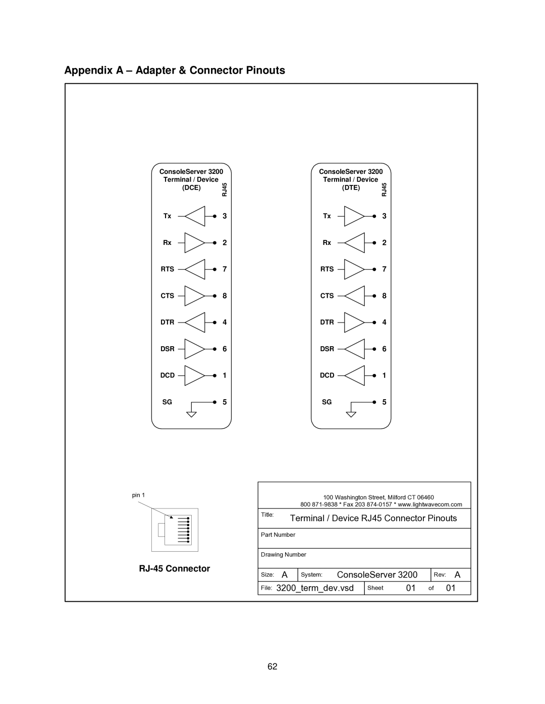
ConsoleServer 3200 Terminal / Device
| (DCE) |
| RJ45 | ||
|
|
| |||
Tx |
|
|
|
| 3 |
|
|
|
| ||
Rx |
|
|
|
| 2 |
|
|
|
| ||
RTS |
|
|
|
| 7 |
|
|
|
| ||
CTS |
|
|
|
| 8 |
|
|
|
| ||
DTR |
|
|
|
| 4 |
|
|
|
| ||
DSR |
|
|
|
| 6 |
|
|
|
| ||
DCD |
|
|
|
| 1 |
|
|
|
| ||
SG |
|
|
|
| 5 |
|
|
|
| ||
|
|
|
|
|
|
ConsoleServer 3200 Terminal / Device
| (DTE) |
| RJ45 | ||
|
|
| |||
Tx |
|
|
|
| 3 |
|
|
|
| ||
Rx |
|
|
|
| 2 |
|
|
|
| ||
RTS |
|
|
|
| 7 |
|
|
|
| ||
CTS |
|
|
|
| 8 |
|
|
|
| ||
DTR |
|
|
|
| 4 |
|
|
|
| ||
DSR |
|
|
|
| 6 |
|
|
|
| ||
DCD |
|
|
|
| 1 |
|
|
|
| ||
SG |
|
|
|
| 5 |
|
|
|
| ||
|
|
|
|
|
|
pin 1
RJ-45 Connector
100 Washington Street, Milford CT 06460
800
Title: | Terminal / Device RJ45 Connector Pinouts | |||||
| ||||||
|
|
|
|
|
| |
Part Number |
|
|
| |||
|
|
|
|
|
| |
Drawing Number |
|
|
| |||
|
|
|
|
|
| |
Size: | A | System: ConsoleServer 3200 |
| Rev: A | ||
File: | 3200_term_dev.vsd | Sheet | 01 | of 01 | ||
62