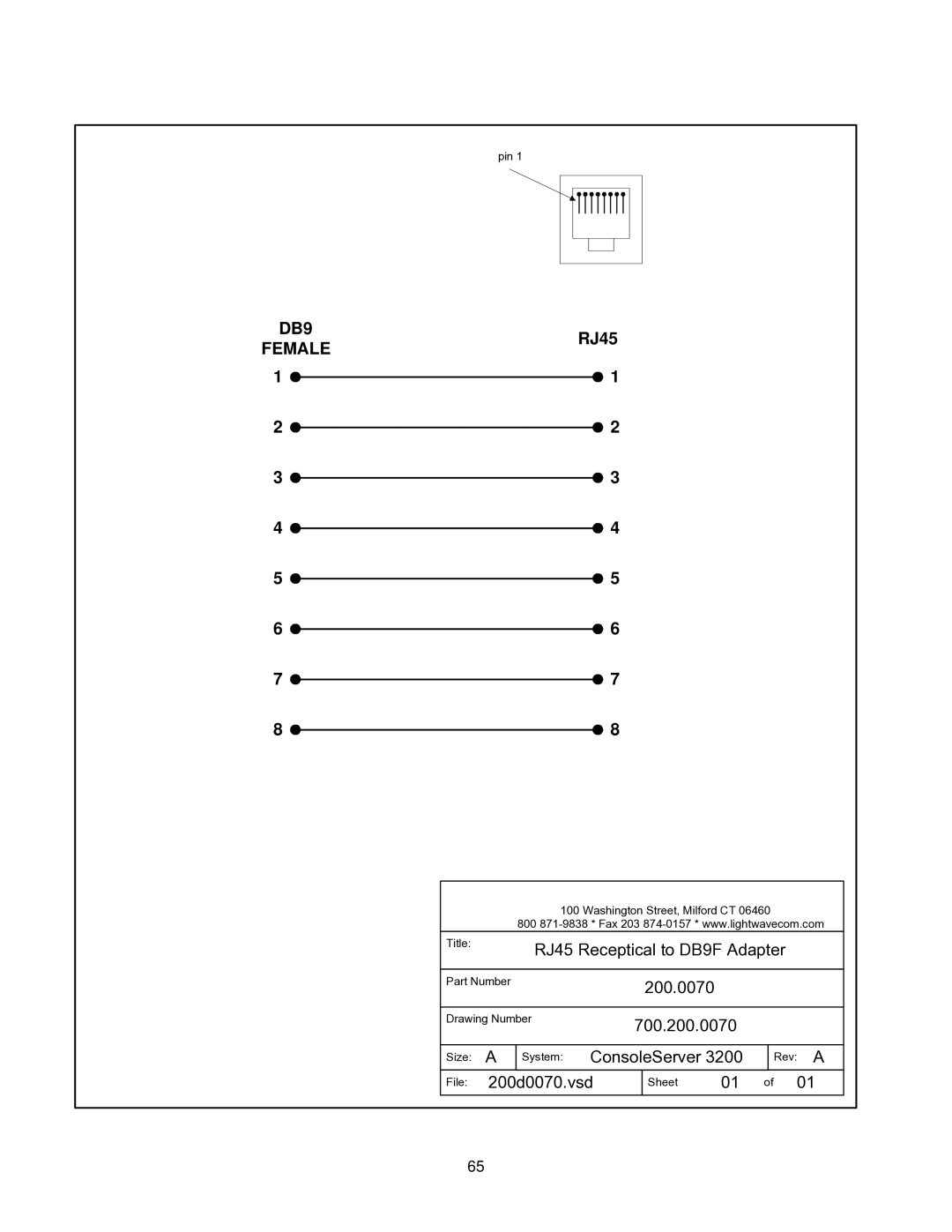
21 June
ConsoleServer
User Manual
100 Washington Street Milford, CT 06460 USA
Lightwave Communications, Inc
800 871-9838 203 878-9838 Fax 203
LCI Asia/Pacific
Security Passwords
Features
Power Supply Module
Access Cards
Error! Bookmark not defined
1.0 Product Description
Remote access via modem card Network access card
1.1 Features
Can be administered both locally and via network
Can update system software via serial or network connection
2.0 System Overview
2.4 Security Passwords
2.1 Connect Up to Thirty-two RS-232C Compatible Ports
2.2 64K FIFO Audit Trail
Page
3.3 Access Cards 3.3.1 Terminal Cards
3.1.1 Power Supply Module
3.0 System Components
3.1 Chassis
3.3.3 Modem Card
4.1 Rack/Desktop Installation
4.0 Installation Instructions 4.1 Items in the Shipping Container
4.4 Power Requirements
4.3 ConsoleServer 3200 Location and Cooling
4.5 Connecting to the Sys Admin Port
Fig. 2 Control Card Layout with DIP Switch Settings
ConsoleServer 3200 serial port default settings
5.0 Connecting Equipment to the ConsoleServer
See Appendix A for further details on connectors and pinouts
5.1 Terminal Card
5.3 Modem Card
5.2 Network Card
Device Card typical adapters and 3200 port configuration
5.4 Device Card
RJ45 to RJ45 Cables
Sun Netra t1 installation Materials
Standard DB9 or DB25 installation Materials
ConsoleServer 3200 device port
device with RS-232-C serial console port
RJ45 Connection to Switch
ConsoleServer 3200 Adapter Quick Checklist
PORT CONFIG
ConsoleServer
Fig. 3 General layout showing terminal port and device port numbers
4 3 2 8 7 6 12 11 10 16 15 14 4 3 2 8 7 6 12 11 10
16 15 14 20 19 18 24 23 22 28 27 26 32 31 30 A
6.1 Power-up Sequence and Basic Use of the Administrator Functions
6.0 ConsoleServer 3200 Administration
6.1.1 Logging In, Serial Connection
6.1.2 Logging In, Network Connection
6.1.3 Logging Out
6.1.4 System Help
LOGGED IN HELP SCREEN
LOGGED OUT HELP SCREEN
Page
6.1.5 Changing the Administration Password
sys adminADDUSER Number of available user records
6.2 Creating and Managing Users 6.2.1 Adding a User ID
Enter case sensitive password PASSWORD
Re-enter case sensitive password PASSWORD
DEVICE DEVICE DEVICE DEVICE DEVICE DEVICE DEVICE DEVICE
Fig. 4 Device Port Numbering
6.2.3 Listing User IDs
6.2.2 Editing a User ID
LISTUSERS
6.2.4 Deleting a User ID
6.3 Devices Command
H I J K L M N O
6.4 Terminals Command
B C D E
6.5 Network Command
The NETWORK command will either display the network settings of the installed network cards or change those settings depending on which command qualifier is used
When used with the /ALL qualifier, the NETWORK command will allow the system administrator to change the network parameters for all the card slots in order. The sys admin will be prompted to enter the IP address, subnet mask, default gateway, secondary route, and bootp settings for each card slot. If ENTER is pressed at the prompt, the value displayed in the prompt will be used. After entering the parameters for each slot, the sys admin will be asked if the new parameters should be used. If NO is entered or just ENTER is pressed, then the previously entered changes will be discarded and the system will move on to the next slot’s parameters. If YES is entered, then the slot’s network parameters will update in control card memory and the control card will send the new parameters immediately to the card in that slot. If the card is a network card, it will immediately acquire the new network parameters and disconnect all telnet sessions to that card. If a terminal card is in the slot, or if the slot is empty, the network parameter update is refused, but the network parameters for that slot will be saved to control card memory
6.6 Modem Command
6.7.1 CONNECTIONS Command
6.7 Status Commands
The above example shows that user KEVIN is logged in on terminal port 01, is connected to device port 01 which is named Server in the ConsoleServer 3200, and is in monitor mode. The list will display the user ID of any logged-in users, the device port to which they are connected, the device name assigned to that port, and the mode of that connection see sections 7.8, 7.9, and 7.10 for an explanation of the various connection modes. If the user is not connected to any device, they shall simply be listed as User Logged-In
6.7.3 VERSION Command
6.7.2 LISTCARDS Command
6.7.4 INFO Command
6.7.6 LOG Command
6.7.5 POWERSTATUS Command
6.8 Sys Admin Session Management Commands
6.8.2 TIMEOUT Command
6.8.1 LINESPERPAGE Command
6.9.1 BREAK Command
6.9 Breaking User Connections
6.9.3 TELNETTIMEOUT Command
6.9.2 FORCELOGOUT Command
6.10 Saving and Restoring System Settings
6.9.4 MODEMTIMEOUT Command
6.11 Changing the System Prompt
6.12 Updating the ConsoleServer 3200 Software
7.2 Network Card
7.0 User Access and Interface 7.1 Terminal Card
7.3.1 The Bye Command
7.4 Overview of Commands
7.3 Modem Card
LOGGED OUT HELP
MONITOR A.K.A. DEVICE MODE HELP
7.5 Logging In and Changing Passwords
7.7 Checking Connections
7.6 Logging Out
7.8 Selecting a Device Port
7.9 Listening to a Server Session
To monitor another users server session, the user must type LISTEN followed by the device port name or number, or select LISTEN TO SERVER and a device port from the pull-down menu. There must be a connection between a user and a device port for another user to be able to listen to the connection. Also, the user must have permission to listen to the server as defined by the system administrator in their user profile. Any user that can log in and has listen permission for a device port may listen to a session on that device port. If the user does not have permission to listen to a server, the ConsoleServer 3200 will display the message NO ACCESS TO DEVICE CHANNEL
7.10.1 Direct Mode Escape Sequence
7.10 Direct Mode
7.11 Using the Buffer
COMMAND
MENU ITEM
FUNCTION
REVERSE
FORWARD
8.0 The Break Generation Sequence
9.0 Displaying System Information
10.0 Front Panel Display Information
Panel 5 press down Panel 6 press down
Panel 3 press down Panel 4 press down
Panel 10 press down Panel 11 press down
Panel 7 press down Panel 8 press down Panel 9 press down
Panel 12 press down
RJ-45 Connector
Appendix A - Adapter & Connector Pinouts
Terminal / Device RJ45 Connector Pinouts
System ConsoleServer
RJ45
DB25
MALE
RJ45 Receptical to DB25M Adapter
RJ45
DB25
FEMALE
RJ45 Receptical to DB25F Adapter
FEMALE
RJ45
RJ45 Receptical to DB9F Adapter
200.0070
Page
Appendix B - Field Update of Console Server 3200 Flash Memory
B.1 Introduction
B.2 Requirements
B.4 Update over Direct Serial Connection
B.3.1 Communications Settings
B.3 Getting Started
sys adminLCIUPDATE
B.5 Update over Network
Download Successful, starting to program Programming Successful
Slot letter Processor number Ex. C1 exit to restart system
local serial connection
B.6 Ending the Flash Update
Slots for programming purposes
TERMINAL TERMINAL TERMINAL
CONTROL
C.3.1 AC Power
Appendix C - System Specifications
C.3.2 DC Power
C.1 Physical
C.4.1
Interface
Terminal and Device
C.4.2
Appendix D -DC Power
48 VDC
Input voltage
Minimum voltage
40 VDC
D.2 Overcurrent Protection
D.3 DC Supply Connector
Appendix E - Command Abbreviations
Terminal, Network, and Modem Commands
command
abbreviation
Hexadecimal
Appendix F - Hexadecimal ASCII Code
Equivalent
Character
Equivalent
Hexadecimal
Character
Hexadecimal
Index
Power Supplies - 1, 5 checking status - 35 Rack Mount
editing direct mode escape sequence - 51-52 logging in
directly interacting with device port - 51-52 editing break sequence
logging out - 47 selecting device