| Part No. |
| June 2001 |
Page 14 of 34 |
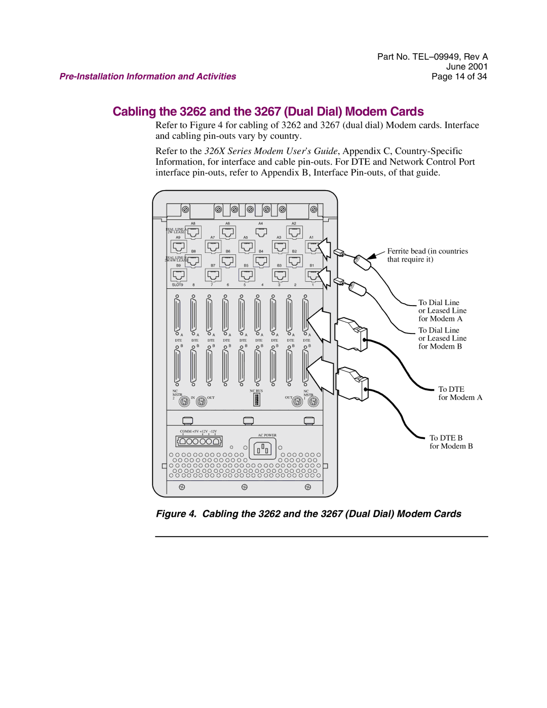
Cabling the 3262 and the 3267 (Dual Dial) Modem Cards
Refer to Figure 4 for cabling of 3262 and 3267 (dual dial) Modem cards. Interface and cabling
Refer to the 326X Series Modem User’s Guide, Appendix C,
| A8 |
| A6 |
| A4 |
| A2 |
|
DIAL LINE A |
|
|
|
|
|
|
|
|
2W LEASE |
|
|
|
|
|
|
|
|
A9 |
| A7 |
| A5 |
| A3 |
| A1 |
| B8 |
| B6 |
| B4 |
| B2 |
|
DIAL LINE B |
|
|
|
|
|
|
|
|
2W/4W LEASE |
|
|
|
|
|
|
|
|
B9 |
| B7 |
| B5 |
| B3 |
| B1 |
SLOT9 | 8 | 7 | 6 | 5 | 4 | 3 | 2 | 1 |
A | A | A | A | A | A | A | A | A |
DTE | DTE | DTE | DTE | DTE | DTE | DTE | DTE | DTE |
B | B | B | B | B | B | B | B | B |
NC |
|
|
|
| NC BUS |
|
| NC |
MSTR | IN | OUT |
|
|
|
| OUT | MSTR |
2 |
|
|
|
| 1 | |||
COMM +5V +12V |
|
| AC POWER |
|
| |||
|
|
|
|
|
|
| ||
Ferrite bead (in countries that require it)
To Dial Line or Leased Line for Modem A
To Dial Line or Leased Line for Modem B
To DTE
for Modem A
To DTE B for Modem B