8. Basic Wiring Diagrams
1) Keypad Panel Operation
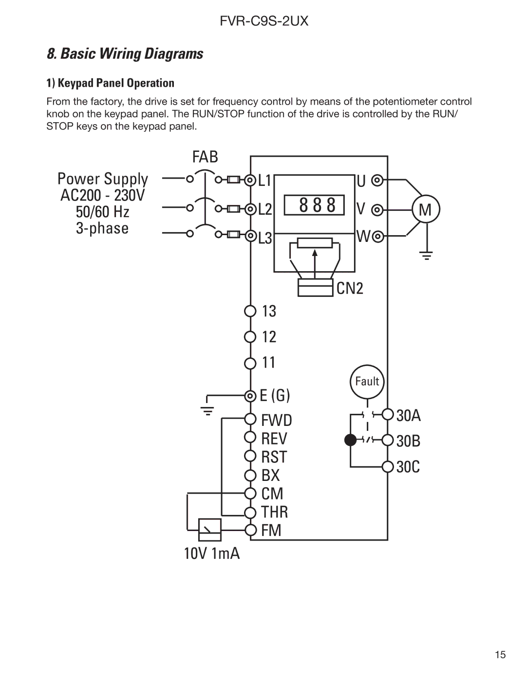
From the factory, the drive is set for frequency control by means of the potentiometer control knob on the keypad panel. The RUN/STOP function of the drive is controlled by the RUN/ STOP keys on the keypad panel.
Power Supply
AC200 - 230V
50/60 Hz
FAB
L1 | U |
|
L2 | 8 8 8 V | M |
L3 | W |
|
| CN2 | |
13 |
| |
12 |
| |
11 |
| |
E (G) | Fault | |
30A | ||
FWD | ||
REV | 30B | |
RST | 30C | |
BX | ||
| ||
CM |
| |
THR |
| |
FM |
|
10V 1mA
15
