CAUTION:
The control circuit terminal wiring should be kept as far as possible from the main circuit wiring to prevent operational error due to noise interference. Never install them in the same duct or conduit. (A separation dis- tance of 4 inches [10cm] or more is recom- mended.) If the control circuit wiring must cross the main circuit wiring, make sure it crosses at a right angle.
Use shielded, twisted wire for the control circuit wiring , which should be as short as possible (65 feet [20m] or less).
Install a surge absorber in parallel with any magnet contactors, solenoids, relays or timer coils, which are close to the drive.
Long wire lengths between the motor and the drive will result in increased capacitance and leakage current. This may cause earlier activation of such protective function as overcurrent protection, overheating protec- tion and electronic thermal overload, or the error in current detection may become large. To avoid these, adjust the length of wiring between the drive and the motor so that is does not exceed the length shown below.
FVRF25 to
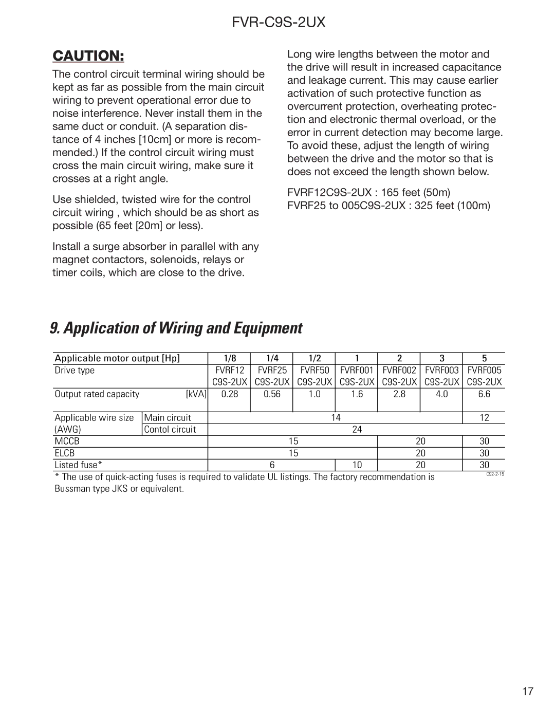
9. Application of Wiring and Equipment
Applicable motor output [Hp] | 1/8 | 1/4 |
| 1/2 |
| 1 | 2 | 3 | 5 | |
Drive type |
| FVRF12 | FVRF25 |
| FVRF50 |
| FVRF001 | FVRF002 | FVRF003 | FVRF005 |
|
| |||||||||
Output rated capacity | [kVA] | 0.28 | 0.56 |
| 1.0 |
| 1.6 | 2.8 | 4.0 | 6.6 |
|
|
|
|
|
|
|
|
|
|
|
Applicable wire size | Main circuit |
|
|
|
| 14 |
|
| 12 | |
(AWG) | Contol circuit |
|
|
|
| 24 |
|
|
| |
MCCB |
|
|
| 15 |
|
| 20 | 30 | ||
ELCB |
|
|
| 15 |
|
| 20 | 30 | ||
Listed fuse* |
|
| 6 |
|
|
| 10 | 20 | 30 | |
* The use of | |
| |
Bussman type JKS or equivalent. |
|
17