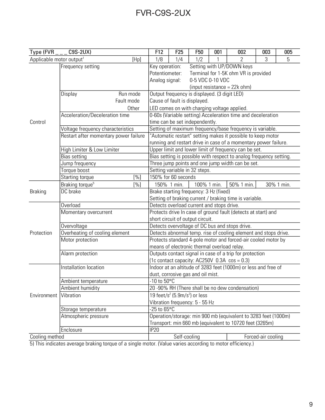
Type (FVR _ _ _ |
| F12 |
| F25 | F50 |
| 001 | 002 |
| 003 |
| 005 | |
Applicable motor output1 | [Hp] | 1/8 |
| 1/4 | 1/2 |
| 1 | 2 |
| 3 |
| 5 | |
| Frequency setting |
| Key operation: | Setting with UP/DOWN keys |
|
|
| ||||||
|
|
| Potentiometer: | Terminal for |
| ||||||||
|
|
| Analog signal: |
|
|
| |||||||
|
|
|
|
|
| (input resistance = 22k ohm) |
|
|
| ||||
| Display | Run mode | Output frequency is displayed. (3 digit LED) |
|
|
| |||||||
|
| Fault mode | Cause of fault is displayed. |
|
|
|
|
|
| ||||
|
| Other | LED comes on with charging voltage applied. |
|
|
| |||||||
| Acceleration/Deceleration time |
| |||||||||||
Control |
|
| time can be set independently. |
|
|
|
|
| |||||
| Voltage frequency characteristics | Setting of maximum frequency/base frequency is variable. |
| ||||||||||
| Restart after momentary power failure | "Automatic restart" setting makes it possible to keep motor |
| ||||||||||
|
|
| running and restart drive in case of a momentary power failure. | ||||||||||
| High Limiter & Low Limiter | Upper limit and lower limit of frequency can be set. |
|
|
| ||||||||
| Bias setting |
| Bias setting is possible with respect to analog frequency setting. | ||||||||||
| Jump frequency |
| Three jump points and one jump width can be set. |
|
|
| |||||||
| Torque boost |
| Setting variable in 32 steps. |
|
|
|
|
|
| ||||
| Starting torque | [%] | 150% for 60 seconds |
|
|
|
|
|
| ||||
| Braking torque5 | [%] | 150% 1 min. | 100% 1 min. | 50% 1 min. |
| 30% 1 min. | ||||||
Braking | DC brake |
| Brake starting frequency: 3 Hz (fixed) |
|
|
| |||||||
|
|
| Setting of braking current / braking time is variable. |
| |||||||||
| Overload |
| Detects overload current and stops drive. |
|
|
| |||||||
| Momentary overcurrent |
| Protects drive In case of ground fault (detects at start) and |
| |||||||||
|
|
| short circuit of output circuit. |
|
|
|
|
|
| ||||
| Overvoltage |
| Detects overvoltage of DC bus and stops drive. |
|
|
| |||||||
Protection | Overheating of cooling element | Detects abnormal temp. rise of cooling element and stops drive. | |||||||||||
| Motor protection |
| Protects standard | ||||||||||
|
|
| means of electronic thermal overload relay. |
|
|
| |||||||
| Alarm protection |
| Outputs contact signal in case of a trip for protection |
| |||||||||
|
|
| (1c contact capacity: AC250V | 0.3A | cos = 0.3) |
|
|
| |||||
| Installation location |
| Indoor at an altitude of 3283 feet (1000m) or less and free of |
| |||||||||
|
|
| dust, corrosive gas and oil mist. |
|
|
|
|
| |||||
| Ambient temperature |
|
|
|
|
|
|
|
|
|
| ||
| Ambient humidity |
| 20 |
|
|
| |||||||
Environment | Vibration |
| 19 feet/s2 (5.9m/s2) or less |
|
|
|
|
|
| ||||
|
|
| Vibration frequency: 5 - 55 Hz |
|
|
|
|
|
| ||||
| Storage temperature |
|
|
|
|
|
|
|
|
|
| ||
| Atmospheric pressure |
| Operation/storage: min 900 mb (equivalent to 3283 feet (1000m) | ||||||||||
|
|
| Transport: min 660 mb (equivalent to 10720 feet (3265m) |
| |||||||||
| Enclosure |
| IP20 |
|
|
|
|
|
|
|
|
| |
Cooling method |
|
|
|
| |||||||||
5) This indicates average braking torque of a single motor. (Value varies according to motor efficiency.)
9
