10. Terminal Function Explanation
Terminal Function Explanation
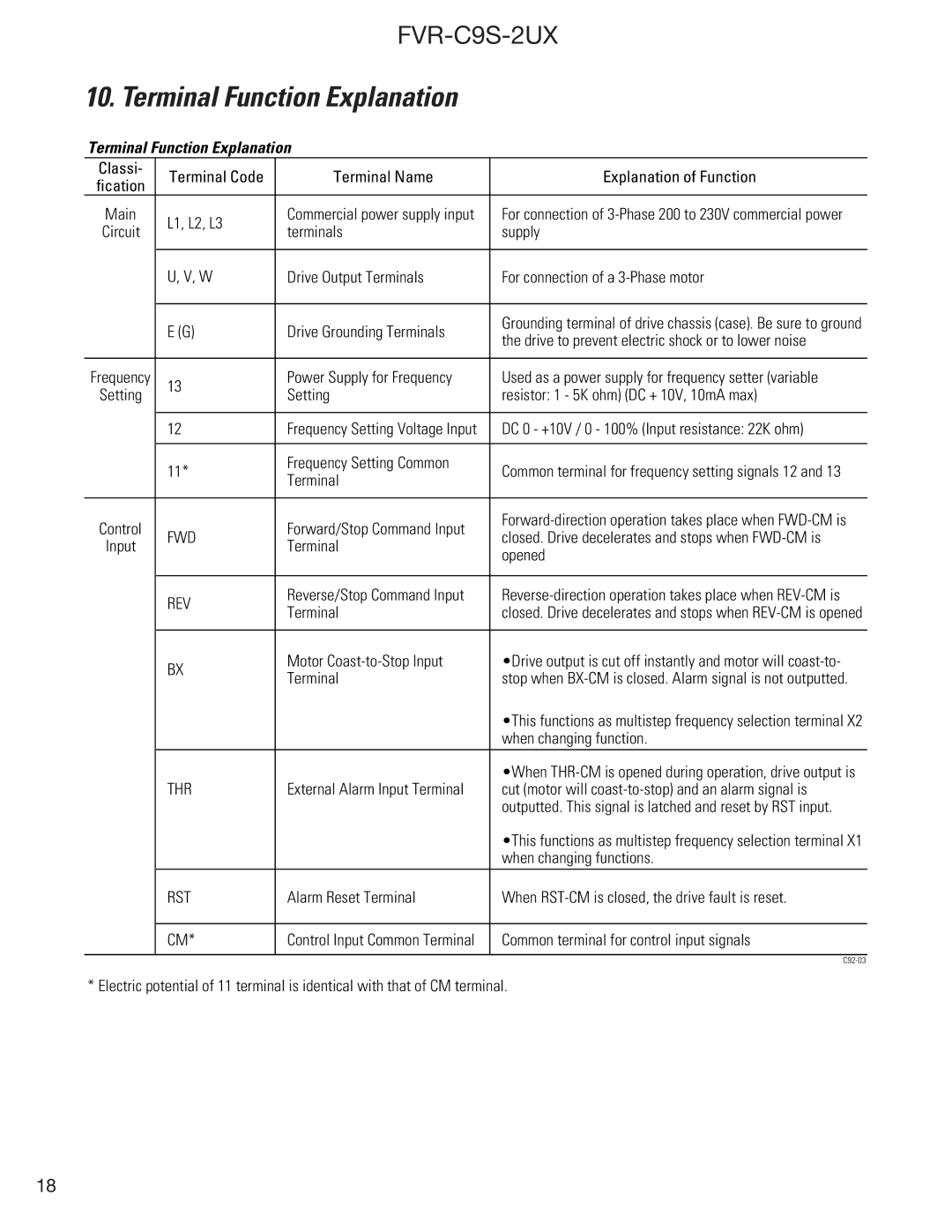
Classi- | Terminal Code | Terminal Name | Explanation of Function | |
fication | ||||
|
|
| ||
Main | L1, L2, L3 | Commercial power supply input | For connection of | |
Circuit | terminals | supply | ||
| ||||
|
|
|
| |
| U, V, W | Drive Output Terminals | For connection of a | |
|
|
|
| |
| E (G) | Drive Grounding Terminals | Grounding terminal of drive chassis (case). Be sure to ground | |
| the drive to prevent electric shock or to lower noise | |||
|
|
| ||
|
|
|
| |
Frequency | 13 | Power Supply for Frequency | Used as a power supply for frequency setter (variable | |
Setting | Setting | resistor: 1 - 5K ohm) (DC + 10V, 10mA max) | ||
| ||||
|
|
|
| |
| 12 | Frequency Setting Voltage Input | DC 0 - +10V / 0 - 100% (Input resistance: 22K ohm) | |
|
|
|
| |
| 11* | Frequency Setting Common | Common terminal for frequency setting signals 12 and 13 | |
| Terminal | |||
|
|
| ||
|
|
|
| |
Control | FWD | Forward/Stop Command Input | ||
closed. Drive decelerates and stops when | ||||
Input | Terminal | |||
| opened | |||
|
|
| ||
|
|
|
| |
| REV | Reverse/Stop Command Input | ||
| Terminal | closed. Drive decelerates and stops when | ||
|
| |||
|
|
|
| |
| BX | Motor | •Drive output is cut off instantly and motor will | |
| Terminal | stop when | ||
|
| |||
|
|
| •This functions as multistep frequency selection terminal X2 | |
|
|
| when changing function. | |
|
|
| •When | |
| THR | External Alarm Input Terminal | cut (motor will | |
|
|
| outputted. This signal is latched and reset by RST input. | |
|
|
| •This functions as multistep frequency selection terminal X1 | |
|
|
| when changing functions. | |
| RST | Alarm Reset Terminal | When | |
|
|
|
| |
| CM* | Control Input Common Terminal | Common terminal for control input signals | |
|
|
|
| |
|
|
|
* Electric potential of 11 terminal is identical with that of CM terminal.
18