11. Operation
Pre-Operation Inspection
•Check for wiring errors.
•Check that all loose wire stands, metal chips and unnecessary screws, etc. have been removed.
•Check that no screws, terminals, etc. are loose.
•Check that the wire ends of crimp terminal are not in contact with other terminals.
•The drive is shipped with a factory in- stalled jumper, between
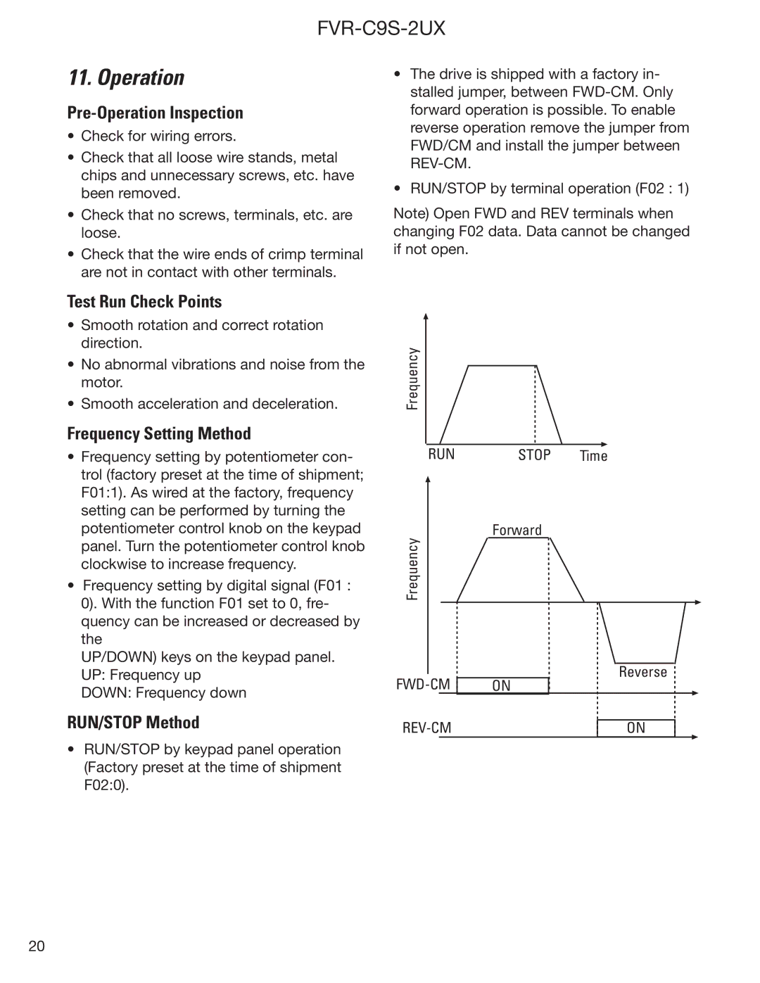
•RUN/STOP by terminal operation (F02 : 1)
Note) Open FWD and REV terminals when changing F02 data. Data cannot be changed if not open.
Test Run Check Points
•Smooth rotation and correct rotation direction.
•No abnormal vibrations and noise from the motor.
•Smooth acceleration and deceleration.
Frequency Setting Method
•Frequency setting by potentiometer con- trol (factory preset at the time of shipment; F01:1). As wired at the factory, frequency setting can be performed by turning the potentiometer control knob on the keypad panel. Turn the potentiometer control knob clockwise to increase frequency.
•Frequency setting by digital signal (F01 : 0). With the function F01 set to 0, fre- quency can be increased or decreased by the
UP/DOWN) keys on the keypad panel. UP: Frequency up
DOWN: Frequency down
RUN/STOP Method
•RUN/STOP by keypad panel operation (Factory preset at the time of shipment F02:0).
Frequency
RUN
Frequency
STOP Time
Forward
Reverse
ON
ON
20