2) External Signal Operation
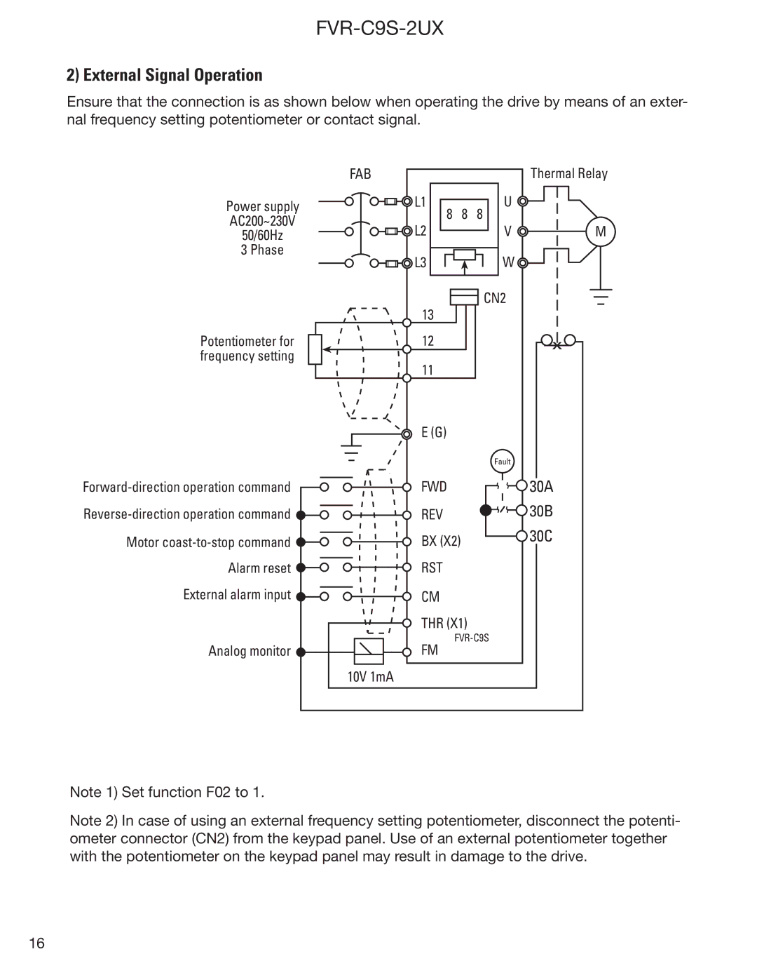
Ensure that the connection is as shown below when operating the drive by means of an exter- nal frequency setting potentiometer or contact signal.
Power supply
AC200~230V
50/60Hz
3 Phase
FAB
![]()
![]()
![]() L1
L1
![]()
![]()
![]() L2
L2
![]()
![]()
![]() L3
L3
8 8 8
Thermal Relay
U![]()
V![]() M W
M W ![]()
Potentiometer for frequency setting
![]()
Motor ![]()
Alarm reset ![]()
External alarm input ![]()
Analog monitor ![]()
Note 1) Set function F02 to 1.
13 | CN2 |
| |
12 | x |
11 |
|
E (G) |
|
| Fault |
FWD | 30A |
REV | 30B |
BX (X2) | 30C |
RST |
|
CM |
|
THR (X1) |
|
| |
FM |
|
10V 1mA
Note 2) In case of using an external frequency setting potentiometer, disconnect the potenti- ometer connector (CN2) from the keypad panel. Use of an external potentiometer together with the potentiometer on the keypad panel may result in damage to the drive.
16