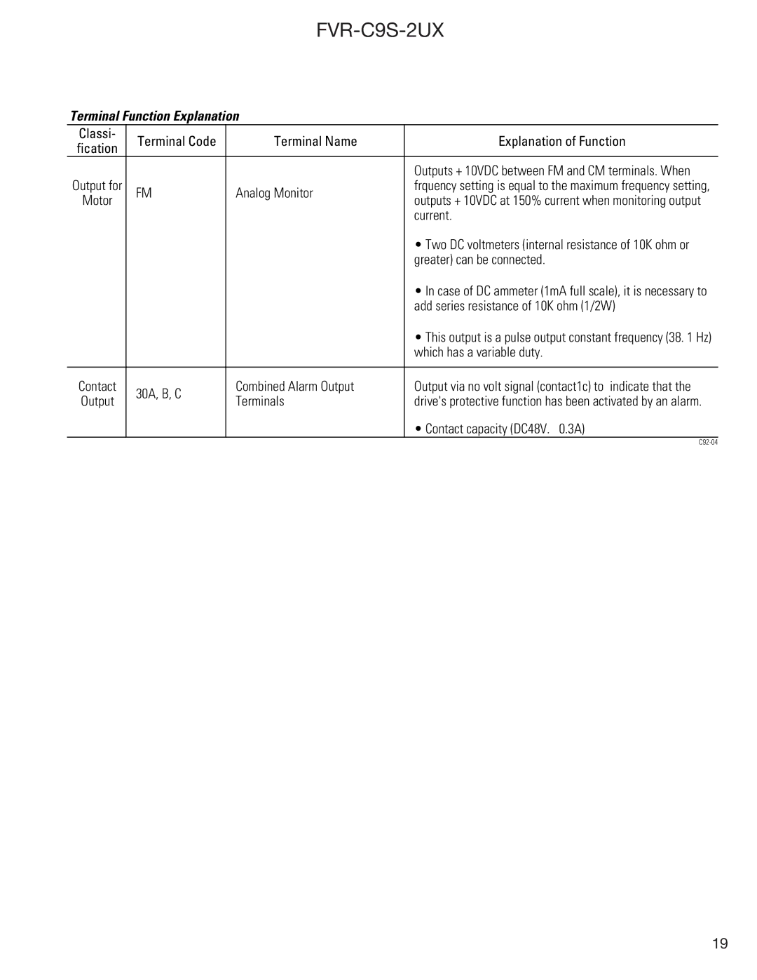
Terminal Function Explanation
Classi- | Terminal Code | Terminal Name | Explanation of Function | |
fication | ||||
|
|
| ||
Output for |
|
| Outputs + 10VDC between FM and CM terminals. When | |
FM | Analog Monitor | frquency setting is equal to the maximum frequency setting, | ||
Motor | outputs + 10VDC at 150% current when monitoring output | |||
|
| |||
|
|
| current. | |
|
|
| • Two DC voltmeters (internal resistance of 10K ohm or | |
|
|
| greater) can be connected. | |
|
|
| • In case of DC ammeter (1mA full scale), it is necessary to | |
|
|
| add series resistance of 10K ohm (1/2W) | |
|
|
| • This output is a pulse output constant frequency (38. 1 Hz) | |
|
|
| which has a variable duty. | |
|
|
|
| |
Contact | 30A, B, C | Combined Alarm Output | Output via no volt signal (contact1c) to indicate that the | |
Output | Terminals | drive's protective function has been activated by an alarm. | ||
| ||||
|
|
| • Contact capacity (DC48V. 0.3A) | |
|
|
|
19
