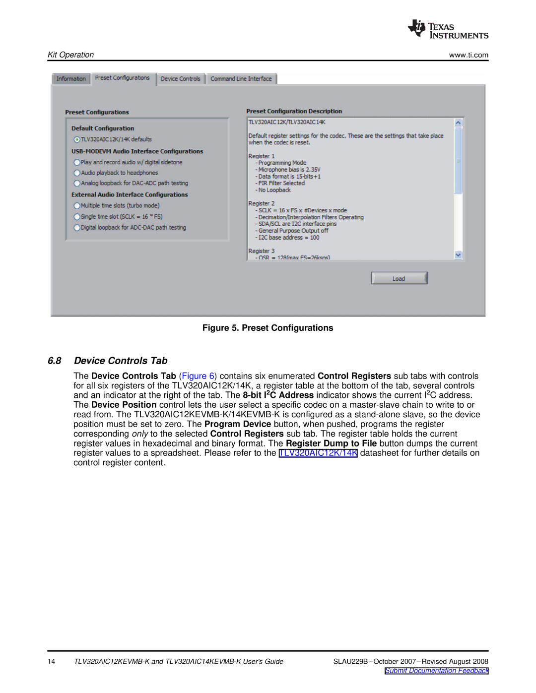
Figure 5. Preset Configurations
6.8Device Controls Tab
The Device Controls Tab (Figure 6) contains six enumerated Control Registers sub tabs with controls
for all six registers of the TLV320AIC12K/14K, a register table at the bottom of the tab, several controls and an indicator at the right of the tab. The 8-bit I2C Address indicator shows the current I2C address. The Device Position control lets the user select a specific codec on a master-slave chain to write to or read from. The TLV320AIC12KEVMB-K/14KEVMB-K is configured as a stand-alone slave, so the device position must be set to zero. The Program Device button, when pushed, programs the register corresponding only to the selected Control Registers sub tab. The register table holds the current register values in hexadecimal and binary format. The Register Dump to File button dumps the current register values to a spreadsheet. Please refer to the TLV320AIC12K/14K datasheet for further details on control register content.
14 | TLV320AIC12KEVMB-K and TLV320AIC14KEVMB-K User's Guide | SLAU229B–October 2007–Revised August 2008 |
Submit Documentation Feedback