Please refer to Appendix A for details. Note that the ring contact in J8 is not connected.
c.MICIN with external common mode (pseudo-differential) - In this mode, the single ended input is connected through ac-coupling to MICIN and the bias voltage used to generate the signal is also ac coupled to INM1. To use this mode, jumper W11 must be installed on pins 1-2. Jumper W12 must be installed if using the on-board electret microphone (MK1), otherwise a microphone can be connected to J8. Please refer to Appendix A for details. Note that the ring contact in J8 is not connected.
d.INP/M2 - selects input 2 as the input source (connected to screw terminal J9).
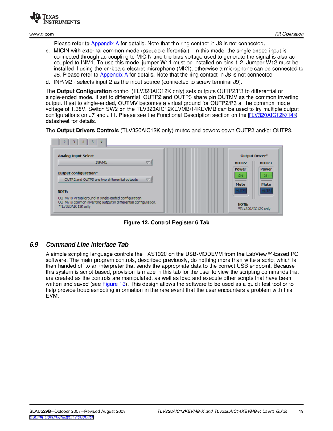
The Output Configuration control (TLV320AIC12K only) sets outputs OUTP2/P3 to differential or single-ended mode. If set to differential, OUTP2 and OUTP3 share pin OUTMV as the common inverting output. If set to single-ended, OUTMV becomes a virtual ground for OUTP2/P3 at the common mode voltage of 1.35V. Switch SW2 on the TLV320AIC12KEVMB/14KEVMB can be used to try multiple output configurations on J7 and J11. Please see the Functional Description section on the TLV320AIC12K/14K datasheet for details.
The Output Drivers Controls (TLV320AIC12K only) mutes and powers down OUTP2 and/or OUTP3.
Figure 12. Control Register 6 Tab
6.9Command Line Interface Tab
A simple scripting language controls the TAS1020 on the USB-MODEVM from the LabView™-based PC software. The main program controls, described previously, do nothing more than write a script which is then handed off to an interpreter that sends the appropriate data to the correct USB endpoint. Because this system is script-based, provision is made in this tab for the user to view the scripting commands that are created as the controls are manipulated, as well as load and execute other scripts that have been written and saved (see Figure 13). This design allows the software to be used as a quick test tool or to help provide troubleshooting information in the rare event that the user encounters a problem with this EVM.
SLAU229B–October 2007–Revised August 2008 | TLV320AIC12KEVMB-K and TLV320AIC14KEVMB-K User's Guide | 19 |
Submit Documentation Feedback