www.ti.com | Kit Operation |
Figure 8. Control Register 2 Tab
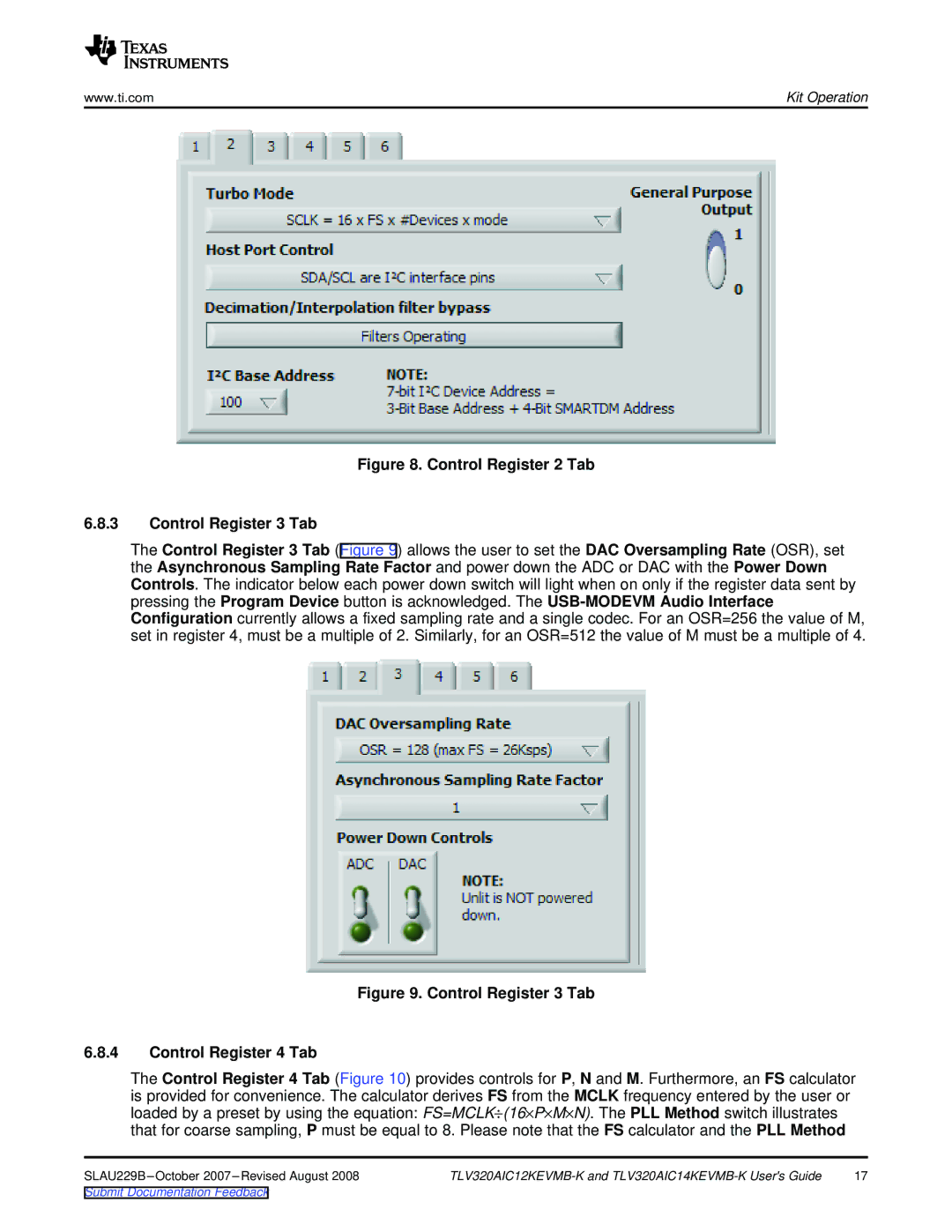
6.8.3Control Register 3 Tab
The Control Register 3 Tab (Figure 9) allows the user to set the DAC Oversampling Rate (OSR), set the Asynchronous Sampling Rate Factor and power down the ADC or DAC with the Power Down Controls. The indicator below each power down switch will light when on only if the register data sent by pressing the Program Device button is acknowledged. The
Figure 9. Control Register 3 Tab
6.8.4Control Register 4 Tab
The Control Register 4 Tab (Figure 10) provides controls for P, N and M. Furthermore, an FS calculator is provided for convenience. The calculator derives FS from the MCLK frequency entered by the user or loaded by a preset by using the equation: FS=MCLK÷(16×P×M×N). The PLL Method switch illustrates that for coarse sampling, P must be equal to 8. Please note that the FS calculator and the PLL Method
17 |
Submit Documentation Feedback