www.ti.com | Kit Operation |
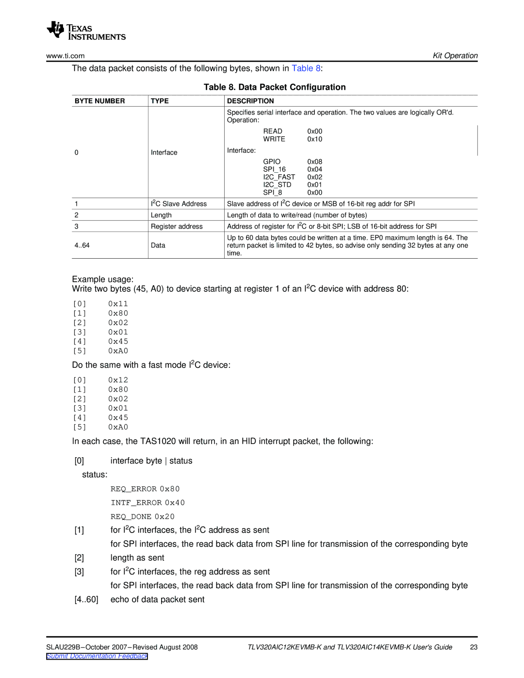
The data packet consists of the following bytes, shown in Table 8:
Table 8. Data Packet Configuration
BYTE NUMBER | TYPE | DESCRIPTION |
|
|
| Specifies serial interface and operation. The two values are logically OR'd. | |
|
| Operation: |
|
|
| READ | 0x00 |
|
| WRITE | 0x10 |
0 | Interface | Interface: |
|
|
| GPIO | 0x08 |
|
| SPI_16 | 0x04 |
|
| I2C_FAST | 0x02 |
|
| I2C_STD | 0x01 |
|
| SPI_8 | 0x00 |
1 | I2C Slave Address | Slave address of I2C device or MSB of | |
2 | Length | Length of data to write/read (number of bytes) | |
3 | Register address | Address of register for I2C or | |
|
| Up to 60 data bytes could be written at a time. EP0 maximum length is 64. The | |
4..64 | Data | return packet is limited to 42 bytes, so advise only sending 32 bytes at any one | |
|
| time. |
|
Example usage:
Write two bytes (45, A0) to device starting at register 1 of an I2C device with address 80:
[0]0x11
[1]0x80
[2]0x02
[3]0x01
[4]0x45
[5]0xA0
Do the same with a fast mode I2C device:
[0]0x12
[1]0x80
[2]0x02
[3]0x01
[4]0x45
[5]0xA0
In each case, the TAS1020 will return, in an HID interrupt packet, the following:
[0]interface byte status
status:
REQ_ERROR 0x80 INTF_ERROR 0x40 REQ_DONE 0x20
[1]for I2C interfaces, the I2C address as sent
for SPI interfaces, the read back data from SPI line for transmission of the corresponding byte
[2]length as sent
[3]for I2C interfaces, the reg address as sent
for SPI interfaces, the read back data from SPI line for transmission of the corresponding byte
[4..60] echo of data packet sent
23 |
Submit Documentation Feedback