4Power Supplies
J3 provides connection to the common power bus for the TLV320AIC12KEVMB/14KEVMB. Power is supplied on the pins listed in Table 4.
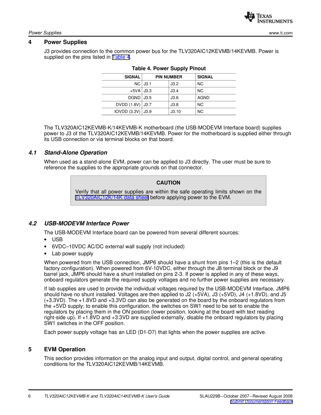
Table 4. Power Supply Pinout
SIGNAL | | PIN NUMBER | SIGNAL |
NC | J3.1 | J3.2 | NC |
+5VA | J3.3 | J3.4 | NC |
DGND | J3.5 | J3.6 | AGND |
DVDD (1.8V) | J3.7 | J3.8 | NC |
IOVDD (3.3V) | J3.9 | J3.10 | NC |
The TLV320AIC12KEVMB-K/14KEVMB-K motherboard (the USB-MODEVM Interface board) supplies power to J3 of the TLV320AIC12KEVMB/14KEVMB. Power for the motherboard is supplied either through its USB connection or via terminal blocks on that board.
4.1Stand-Alone Operation
When used as a stand-alone EVM, power can be applied to J3 directly. The user must be sure to reference the supplies to the appropriate grounds on that connector.
CAUTION
Verify that all power supplies are within the safe operating limits shown on the
TLV320AIC12K/14K data sheet before applying power to the EVM.
4.2USB-MODEVM Interface Power
The USB-MODEVM Interface board can be powered from several different sources:
∙USB
∙6VDC–10VDC AC/DC external wall supply (not included)
∙Lab power supply
When powered from the USB connection, JMP6 should have a shunt from pins 1–2 (this is the default factory configuration). When powered from 6V-10VDC, either through the J8 terminal block or the J9 barrel jack, JMP6 should have a shunt installed on pins 2-3. If power is applied in any of these ways, onboard regulators generate the required supply voltages and no further power supplies are necessary.
If lab supplies are used to provide the individual voltages required by the USB-MODEVM Interface, JMP6 should have no shunt installed. Voltages are then applied to J2 (+5VA), J3 (+5VD), J4 (+1.8VD), and J5 (+3.3VD). The +1.8VD and +3.3VD can also be generated on the board by the onboard regulators from the +5VD supply; to enable this configuration, the switches on SW1 need to be set to enable the regulators by placing them in the ON position (lower position, looking at the board with text reading right-side up). If +1.8VD and +3.3VD are supplied externally, disable the onboard regulators by placing SW1 switches in the OFF position.
Each power supply voltage has an LED (D1-D7) that lights when the power supplies are active.
5EVM Operation
This section provides information on the analog input and output, digital control, and general operating conditions for the TLV320AIC12KEVMB/14KEVMB.
6 | TLV320AIC12KEVMB-K and TLV320AIC14KEVMB-K User's Guide | SLAU229B–October 2007–Revised August 2008 |