www.ti.com | EVM Overview |
1 EVM Overview
1.1Features
∙
∙
∙Intuitive evaluation software
∙Easy interfacing to multiple analog sources
∙Analog output signals from the TLV320AIC12K/14K are available on top and bottom connectors.
∙
∙Digital control signals can be applied directly to top and bottom connectors.
1.2Introduction
The
2Analog Interface
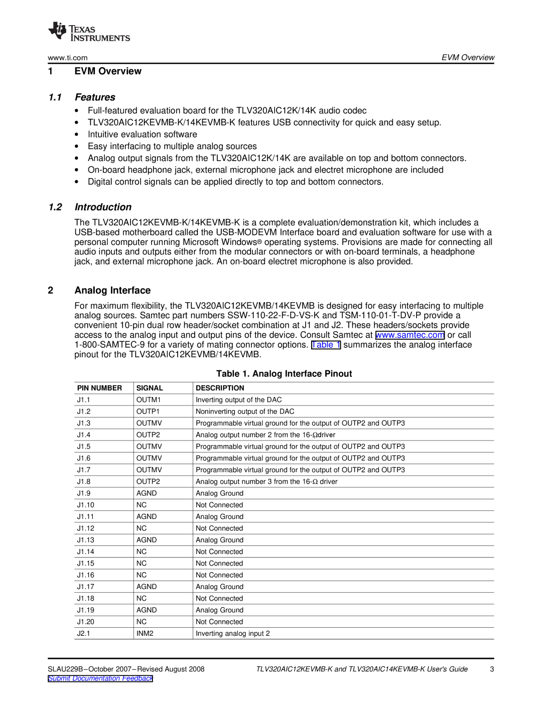
For maximum flexibility, the TLV320AIC12KEVMB/14KEVMB is designed for easy interfacing to multiple analog sources. Samtec part numbers
|
| Table 1. Analog Interface Pinout |
| |
PIN NUMBER | SIGNAL | DESCRIPTION |
|
|
J1.1 | OUTM1 | Inverting output of the DAC |
| |
J1.2 | OUTP1 | Noninverting output of the DAC |
| |
J1.3 | OUTMV | Programmable virtual ground for the output of OUTP2 and OUTP3 |
| |
J1.4 | OUTP2 | Analog output number 2 from the |
| |
J1.5 | OUTMV | Programmable virtual ground for the output of OUTP2 and OUTP3 |
| |
J1.6 | OUTMV | Programmable virtual ground for the output of OUTP2 and OUTP3 |
| |
J1.7 | OUTMV | Programmable virtual ground for the output of OUTP2 and OUTP3 |
| |
J1.8 | OUTP2 | Analog output number 3 from the |
| |
J1.9 | AGND | Analog Ground |
|
|
J1.10 | NC | Not Connected |
|
|
J1.11 | AGND | Analog Ground |
|
|
J1.12 | NC | Not Connected |
|
|
J1.13 | AGND | Analog Ground |
|
|
J1.14 | NC | Not Connected |
|
|
J1.15 | NC | Not Connected |
|
|
J1.16 | NC | Not Connected |
|
|
J1.17 | AGND | Analog Ground |
|
|
J1.18 | NC | Not Connected |
|
|
J1.19 | AGND | Analog Ground |
|
|
J1.20 | NC | Not Connected |
|
|
J2.1 | INM2 | Inverting analog input 2 |
| |
3 | ||||
Submit Documentation Feedback |
|
|
| |
