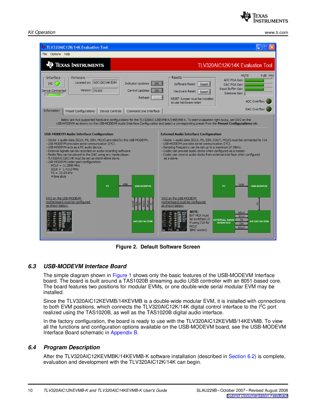
Figure 2. Default Software Screen
6.3USB-MODEVM Interface Board
The simple diagram shown in Figure 1 shows only the basic features of the USB-MODEVM Interface board. The board is built around a TAS1020B streaming audio USB controller with an 8051-based core. The board features two positions for modular EVMs, or one double-wide serial modular EVM may be installed.
Since the TLV320AIC12KEVMB/14KEVMB is a double-wide modular EVM, it is installed with connections to both EVM positions, which connects the TLV320AIC12K/14K digital control interface to the I2C port realized using the TAS1020B, as well as the TAS1020B digital audio interface.
In the factory configuration, the board is ready to use with the TLV320AIC12KEVMB/14KEVMB. To view all the functions and configuration options available on the USB-MODEVM board, see the USB-MODEVM Interface Board schematic in Appendix B.
6.4Program Description
After the TLV320AIC12KEVMBK/14KEVMB-K software installation (described in Section 6.2) is complete, evaluation and development with the TLV320AIC12K/14K can begin.
10 | TLV320AIC12KEVMB-K and TLV320AIC14KEVMB-K User's Guide | SLAU229B–October 2007–Revised August 2008 |
Submit Documentation Feedback