www.ti.com | Kit Operation |
5.1Analog Input
The analog input sources can be applied directly to J2 (top or bottom side). The analog inputs may also be accessed through J8 and screw terminals J9 and J10.
5.2Analog Output
The analog outputs from the TLV320AIC12K/14K are available on J1 (top or bottom). They also may be accessed through J6 and J7 or J11. Note that the TLV320AIC14K only has one (differential) output which can be accessed from J1 or screw terminal J6.
5.3Digital Control
The digital control signals can be applied directly to J4 and J5 (top or bottom side). The modular TLV320AIC12KEVMB/14KEVMB can also be connected directly to the
5.4Default Jumper Locations
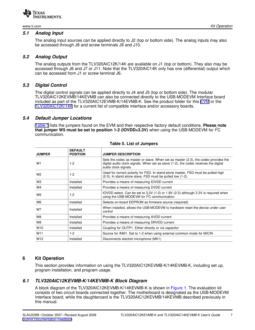
Table 5 lists the jumpers found on the EVM and their respective factory default conditions. Please note that jumper W5 must be set to position
|
| Table 5. List of Jumpers |
| DEFAULT |
|
JUMPER | POSITION | JUMPER DESCRIPTION |
|
| Sets the codec as master or slave. When set as master |
W1 | digital audio clock signals. When set as slave | |
|
| audio clock signals. |
W2 | |
W3 | Installed |
W4 | Installed |
W5 |
Used for correct polarity for FSD. In
![]() Provides a means of measuring IOVDD current
Provides a means of measuring IOVDD current
Provides a means of measuring DVDD current
IOVDD select. Can be set to 3.3V
W6 | Installed | Selects | |
W7 | Installed | When installed, allows the | |
control | |||
|
| ||
W8 | Installed | Provides a means of measuring AVDD current | |
W9 | Installed | Provides a means of measuring DRVDD current | |
W10 | Installed | Coupling for OUTP1. Either directly or via capacitor | |
W11 | Source for INM1. Set to | ||
W12 | Installed | Disconnects electret microphone (MK1) |
6Kit Operation
This section provides information on using the
6.1TLV320AIC12KEVMB-K/14KEVMB-K Block Diagram
A block diagram of the
7 |
Submit Documentation Feedback
