Manuals
/
GBC
/
Power Tools
/
Laminate Trimmer
GBC
F - 160 CE
manual
Web Diagram Blank
Models:
F - 160 CE
1
88
127
127
Download
127 pages
9.05 Kb
85
86
87
88
89
90
91
92
Troubleshooting
Specs
Install
Chart
Default settings
Symbols
Connecting power
Warranty
Dimension
Wave problems
Page 88
Image 88
F - 160 CE Operation and Maintenance Manual
Applications
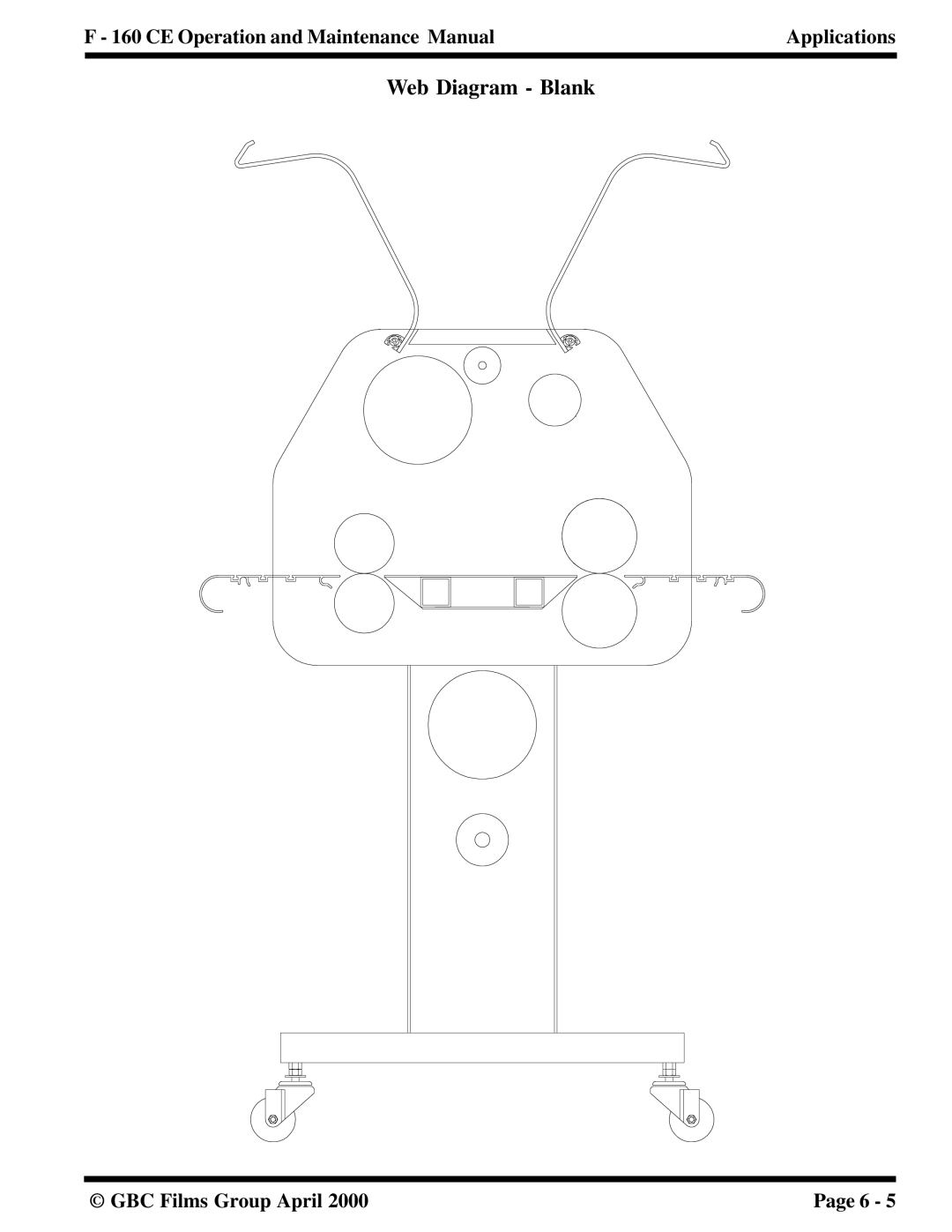
Web Diagram - Blank
© GBC Films Group April 2000
Page 6 - 5
Page 87
Page 89
Page 88
Image 88
Page 87
Page 89
Contents
CE Operation Maintenance Manual
Table of Contents Safety
Warranty
Specifications
Installation
Installing levelers Leveling Connecting power
Operations
Chart
Front control panel
Applications Parameter charts and diagrams
Pull roller manual nip adjustment
Chart 6.1.1 Temperature conversion chart
Blank chart Blank diagram
Diagram 6 Decal and mount
Diagram 5 Decal and mount
Chart 7 Precoating subtrates
Troubleshooting
Maintenance
This page intentionally left blank
Symbols
F O R M a T I O N
Safety features
Qualified
Safety shield
1 Cabinets and covers
Emergency stop
Stops
Refer to .5.2 Reset the E-CABLE
Emergency cable
Machine. Refer to .5.1 Emergency cable
Machine will only operate if
Front feed table
Front feed table
Label locations
Mucho Cuidado
Safety 160CE Operation and Maintenance Manual
1 Label locations Front
2 Label locations Rear
Limited Warranty
Exclusions to the Warranty
This warranty specifically does not cover
Unauthorized customer alterations will Void this warranty
Qualified
Section General
Section Consumable
Section Function
Electrical
Dimensions
Refer to Figure
82.5 210 cm 135 cm 193 cm 12 cm 71 cm 875
This page intentionally left blank
Pre-installation
Installation CE Operation and Maintenance Manual
6 1.22 m x 2m
Know your machine
3 Front view
Unpacking
Shrink Wrapped
Tools required
To uncrate the laminator
Crated
Moving the laminator
Removing the shrink wrap
Move all packing materials to a safe distance
Accessory Pack contents
Installing levelers
Control side
1 Leveling pad installed
Drive side
Leveling
Front to back control side
2 Front to back drive side
00.0
3 Drive to control side front
Drive to control side front
Connecting power
Turn Main Power to OFF
Machine to lower the upper pull roller
Drive to control side rear
2 Wye three phaseillustrates proper
Proceed with 4.10 Safety check GBC Films Group April
1 Single phase, U.S. and Canada
Safety check Front feed table
Press FWD to set a forward motor direction
Press Stop .GO stops flashing
Stop
S h
Cable
Push
Function check
Control panel
PP R E S S U R E
15.0
00.0
Default settings
Variable speed footswitch
Controls / 28 Footswitch
Unwind shafts and unwind brakes
Upper unwind brake Adjustment dial
Steps e and f will be performed Simultaneously
This page intentionally left blank
CE Operation and Maintenance Manual Operations
Operations CE Operation and Maintenance Manual
R N I N G
Job programming is explained Section
Stop When pressed, stops the rollers and GO becomes white
Panel to Footswitch
Variable speed footswitch
Footswitch to Panel
To raise the safety shield
To lower the safety shield
Iiiiiii
Emergency An emergency
Resume operation
Push
Power
Set up
Film loading
Onceloaded, swing the unwind shaft back into the saddle
Heating
Chart 5.3.1 Measurement chart
For the lower unwind shaft, add 1/4 in . to Measurement
Slow speed helps distribute heat evenly
Job programming
225
Chart 5.4.1 Job save chart
Main roller manual nip adjustment
Manual nip adjustment
Procedure
Excess pressure can damage the laminating
Refer to .5.1 for proper roller Pressure
1 Main roller pressure
Pull roller manual nip adjustment
W N
2 Pull roller pressure
Refer to .5.2 for proper roller Pressure
Removing the table
Replacing the infeed table
Front Support bolt
This page intentionally left blank
Applications
Charts and Diagrams
Chart Temperature conversion chart
120
Parameter Chart Blank
Web Diagram Blank
Parameter Chart 1 Precoating substrates
00.0
Web Diagram 1 Precoating substrate
Parameter Chart 2 Mounting only
Web Diagram 2 Mounting only
Parameter Chart 3 Single sided Sled
Web Diagram 3 Single sided Sled
Parameter Chart 4 Single sided Craft paper
Web Diagram 4 Single sided Craft paper
Parameter Chart 5 Decal and mount Decal
Web Diagram 5 Decal and mount Decal
Parameter Chart 6 Decal and mount Mount
Web Diagram 6 Decal and mount Mount
Parameter Chart 7 Precoating substrates Thermal
Web Diagram 7 Precoating substrate Thermal
Parameter Chart 8 One pass mount and laminate
Web Diagram 8 One pass mount and laminate
Parameter Chart 9 Thermal decal and Mount Decal
Web Diagram 9 Thermal decal and mount Decal
Parameter Chart 10 Thermal decal and Mount Mount
Web Diagram 10 Thermal decal and mount Mount
Parameter Chart 11 Encapsulation
Web Diagram 11 Encapsulation
This page intentionally left blank
Troubleshooting
Wave problems
Problem D waves in the image but not in the laminate
Troubleshooting CE Operation and Maintenance Manual
Film problems
Problem Tunneling
Thermal laminates
Pressure sensitive
Machine problems
My Falcon 160 CE Laminator serial # is
Rollers in the down position
Rolls in the up position
Glossary
Clutch tension Encapsulation
Coiling
Cold laminate
Film
Mount tissue
Main rollers Pull rollers
Media
Mount adhesive
Silvering
Substrate
Tunneling
Unwind
Daily
Maintenance Maintenance Schedule
Monthly
Cleaning the rollers
Semi-Annual Preparation of the laminator
Removing adhesive build up
Cleaning the beads Adhesives, dust and dirt from Rolls
Method
N I T E T H E F U M E S
E E D
Clean the cabinets Cleaning the touch Covers Screen
This page intentionally left blank
Top
Page
Image
Contents