Registers
5.2Direction Register (DIR)
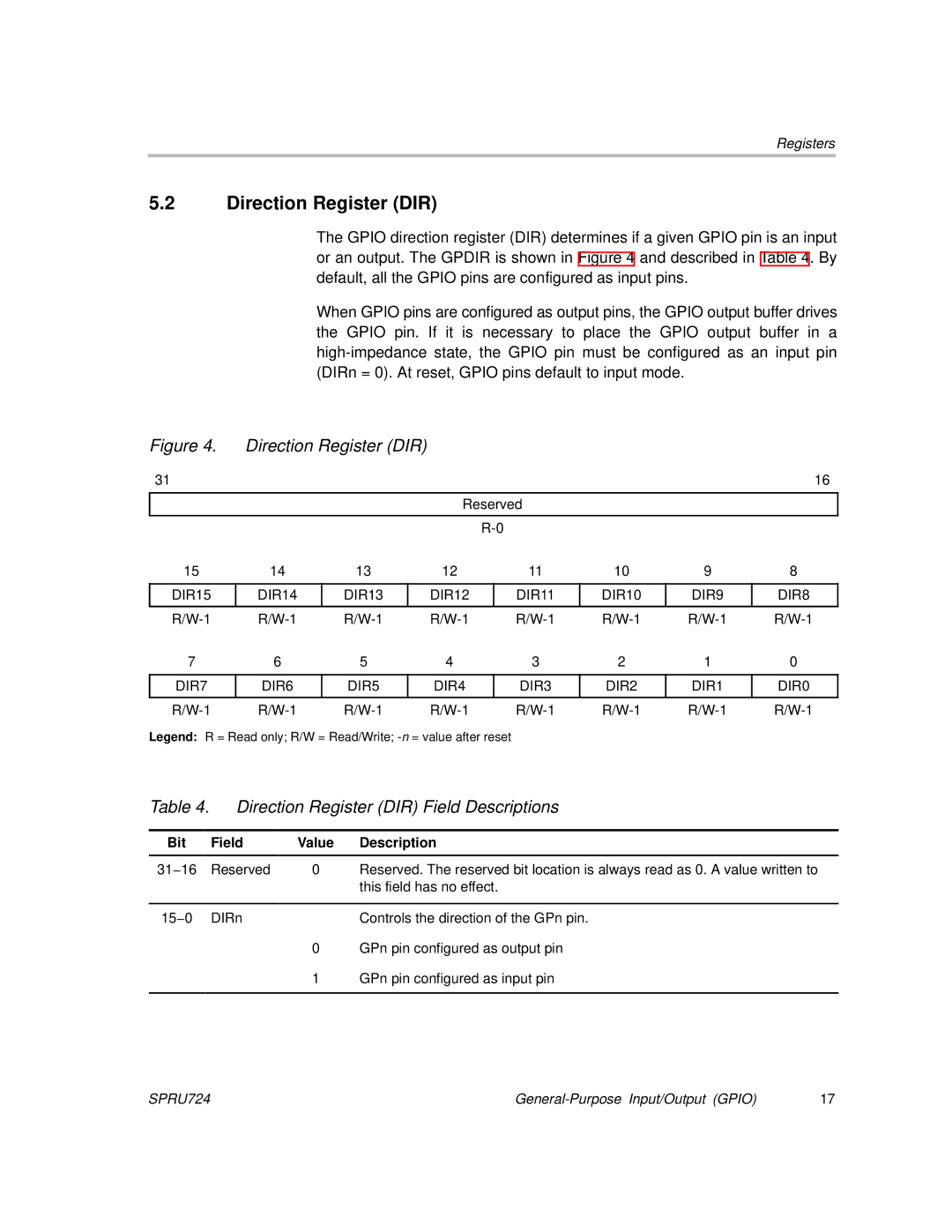
The GPIO direction register (DIR) determines if a given GPIO pin is an input or an output. The GPDIR is shown in Figure 4 and described in Table 4. By default, all the GPIO pins are configured as input pins.
When GPIO pins are configured as output pins, the GPIO output buffer drives the GPIO pin. If it is necessary to place the GPIO output buffer in a
Figure 4. | Direction Register (DIR) |
|
|
|
|
|
| ||
31 |
|
|
|
|
|
|
|
| 16 |
|
|
|
|
|
|
|
|
| |
|
|
|
| Reserved |
|
|
| ||
|
|
|
|
|
|
|
|
|
|
|
|
|
|
|
|
|
| ||
15 | 14 | 13 |
| 12 |
| 11 | 10 | 9 | 8 |
|
|
|
|
|
|
|
|
|
|
DIR15 | DIR14 | DIR13 |
| DIR12 |
| DIR11 | DIR10 | DIR9 | DIR8 |
|
|
|
|
|
|
|
|
|
|
7 | 6 | 5 |
| 4 |
| 3 | 2 | 1 | 0 |
|
|
|
|
|
|
|
| ||
DIR7 | DIR6 | DIR5 |
| DIR4 |
| DIR3 | DIR2 | DIR1 | DIR0 |
|
|
|
|
|
|
|
|
|
|
Legend: R = Read only; R/W = Read/Write; |
|
|
|
| |||||
Table 4. | Direction Register (DIR) Field Descriptions | ||
|
|
|
|
Bit | Field | Value | Description |
|
|
|
|
31−16 | Reserved | 0 | Reserved. The reserved bit location is always read as 0. A value written to |
|
|
| this field has no effect. |
|
|
|
|
15−0 | DIRn |
| Controls the direction of the GPn pin. |
|
| 0 | GPn pin configured as output pin |
|
| 1 | GPn pin configured as input pin |
|
|
|
|
SPRU724 | 17 |
