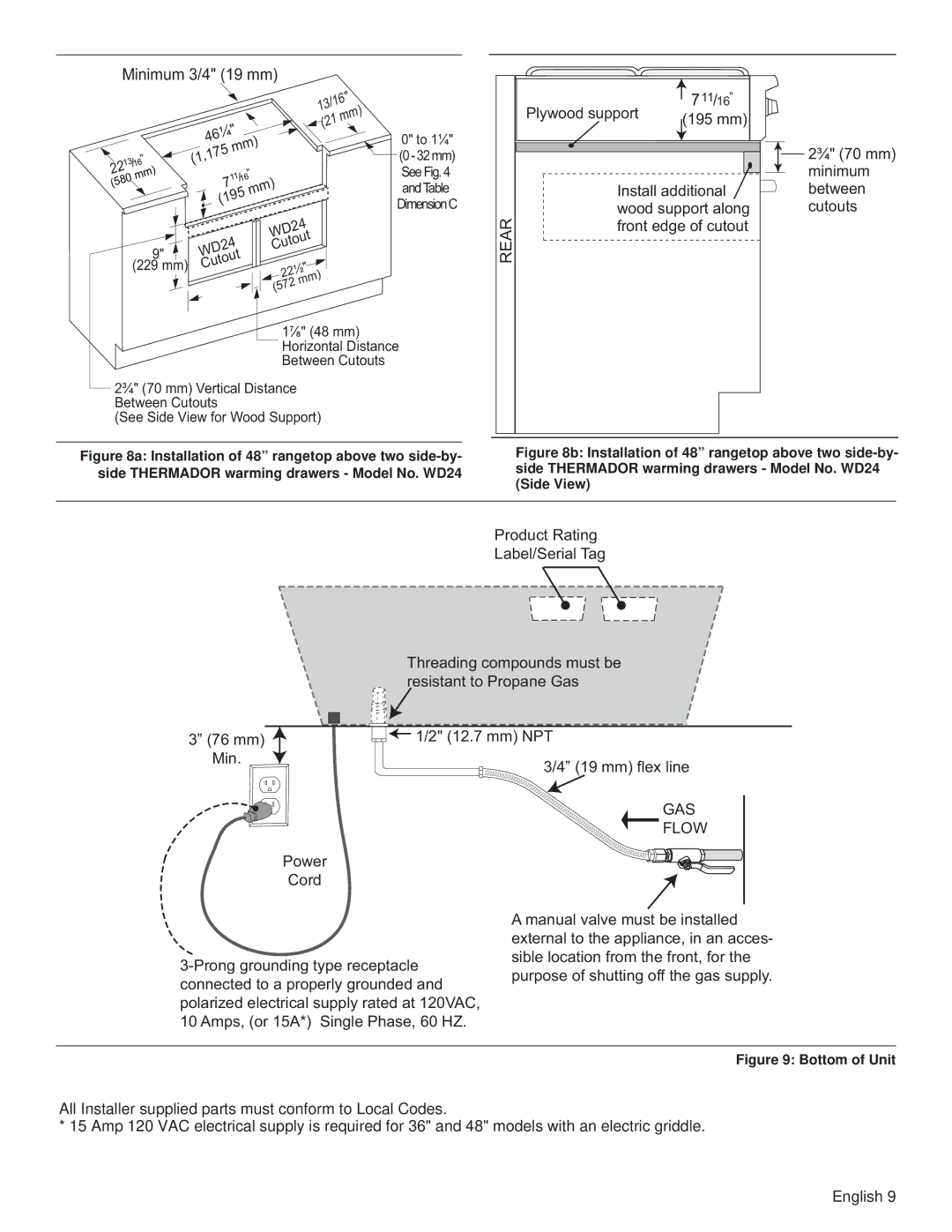
PCG30, PCG48, PCG36 specifications
The Thermador PCG36, PCG48, and PCG30 are beautifully engineered professional-style gas cooktops that stand out for their performance, design, and innovative features. These models embody the ethos of Thermador, which is to provide culinary enthusiasts with the tools they need to create exceptional dishes at home.One of the main features of these cooktops is their powerful Star® Burners. The PCG36 and PCG48 come equipped with up to five burners, including a highly efficient center burner that delivers up to 22,000 BTUs of heat. This powerful burner is ideal for searing, stir-frying, or boiling large pots of water quickly. The precise temperature control provided by these burners allows for a wide range of cooking techniques, from delicate sauces to high-heat frying.
Each model showcases a unique cooking surface design, offering both functionality and aesthetics. The heavy-gauge stainless steel construction not only provides durability but also creates a sleek, sophisticated look suitable for any luxury kitchen. The Cooktop’s continuous cast-iron grates ensure that pots and pans slide effortlessly across the surface, enhancing the overall cooking experience.
In addition to their robust performance, these models are equipped with advanced features such as patented ExtraLow® simmering technology, which delivers ultra-low heat settings perfect for melting chocolate or keeping sauces warm without scalding. This technology is ideal for chefs who require precise control over their cooking temperatures.
The Thermador PCG series also prioritizes safety with features like automatic re-ignition, which ensures that if a burner’s flame is extinguished, it will automatically relight. Safety is paramount, particularly in fast-paced kitchen environments, and this feature provides peace of mind while cooking.
Moreover, one of the standout characteristics of these cooktops is their compatibility with Thermador’s exclusive Freedom® cooktops, which allows for more flexible cooking configurations. This innovative design enables chefs to arrange their cooking stations according to their unique preferences.
In summary, the Thermador PCG36, PCG48, and PCG30 models exemplify precision, durability, and modern design. With their powerful burners, advanced technologies, and safety features, they cater to the demands of both amateur cooks and seasoned chefs. These cooktops are an excellent investment for anyone looking to elevate their culinary experience and kitchen aesthetics.

