HARDWARE BASICS
Installing the Motherboard
HARDWARE BASICS
Fitting the Legs
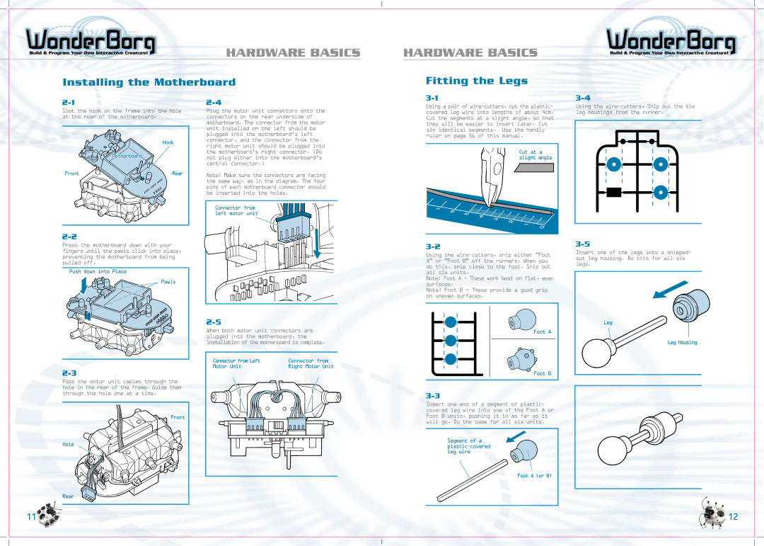
Slot the hook on the frame into the hole at the rear of the motherboard.
Hook
![]()
![]() Motherboard
Motherboard
Front | Rear |
Plug the motor unit connectors onto the connectors on the rear underside of motherboard. The connector from the motor unit installed on the left should be plugged into the motherboard’s left connector, and the connector from the right motor unit should be plugged into the motherboard’s right connector. (Do not plug either into the motherboard’s central connector.)
Note: Make sure the connectors are facing the same way, as in the diagram. The four pins of each motherboard connector should be inserted into the holes.
Connector from left motor unit
Using a pair of
Cut at a slight angle
Using the
Press the motherboard down with your
|
fingers until the pawls click into place, preventing the motherboard from being pulled off.
Push down into Place
Pawls
When both motor unit connectors are plugged into the motherboard, the installation of the motherboard is complete.
Connector from Left | Connector from |
Motor Unit | Right Motor Unit |
Using the
Note: Foot A - These work best on flat, even surfaces.
Note: Foot B - These provide a good grip on uneven surfaces.
Foot A
Insert one of the legs into a snipped- out leg housing. Do this for all six legs.
Leg
Leg Housing
Pass the motor unit cables through the hole in the rear of the frame. Guide them through the hole one at a time.
Foot B
Front
Hole
Rear
11
Insert one end of a segment of plastic- covered leg wire into one of the Foot A or Foot B units, pushing it in as far as it will go. Do the same for all six units.
Segment of a
Foot A (or B)
12