ASSEMBLY
POLY-CARBONATE SAFETY WINDOW
NOTE: This should be done before mounting the main frame.
1.Disconnect gas shock at door. Remove the right side cab door from tractor cab by removing hinge pins.
2.Remove the existing hardware and discard factory glass door.
3.Place small beed of adhesive seal in the botom of the trim lock bubble beed.
4.Install trim lock bubble seal on polycarbonate starting at the cenyer bottom horizontal portion.
5.Install existing hardware removed from glass door on the polycarbonate.
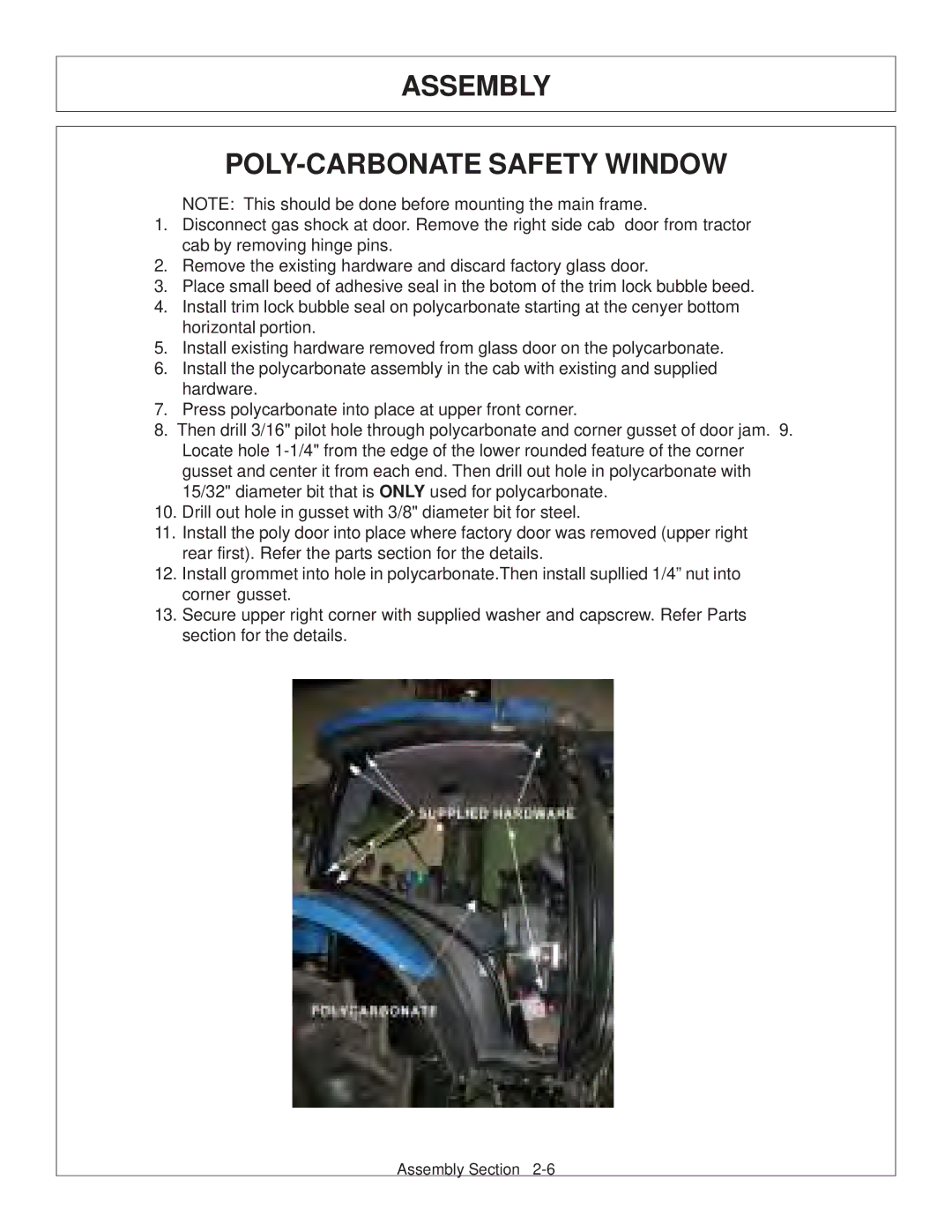
6.Install the polycarbonate assembly in the cab with existing and supplied hardware.
7.Press polycarbonate into place at upper front corner.
8.Then drill 3/16" pilot hole through polycarbonate and corner gusset of door jam. 9. Locate hole
15/32" diameter bit that is ONLY used for polycarbonate.
10.Drill out hole in gusset with 3/8" diameter bit for steel.
11.Install the poly door into place where factory door was removed (upper right rear first). Refer the parts section for the details.
12.Install grommet into hole in polycarbonate.Then install supllied 1/4” nut into corner gusset.
13.Secure upper right corner with supplied washer and capscrew. Refer Parts section for the details.
Assembly Section