3301 N. Louise Ave Sioux Falls, SD
Tiger Corporation
PARTS LISTING WITH MOUNTING AND OPERATING INSTRUCTIONS
TWIN ROTARY ASSEMBLIES
TO THE OWNER / OPERATOR / DEALER
Tiger Corporation
FORWARD
Page
CAUTION - YOUR SAFETY IS AT RISK
TABLE OF CONTENTS
This symbol means
ASSEMBLY / MOUNTING SECTION
Page
SAFETY
SAFETY SECTION
General Safety Instructions and Practices
Practice all usual and customary safe working precautions and
SAFETY
SAFETY
LEA EL INSTRUCTIVO
DANGER
DANGER DANGER
SAFETY
DANGER DANGER DANGER
SG-10
sure you abide by the following rules
SAFETY
DANGER DANGER
SAFETY
SG-20
SG-23
DANGER
SAFETY
DANGER
DANGER
DANGER
SAFETY
Do not put hands or feet under mower decks. Blade Contact can result
DANGER
SAFETY
DANGER
STOP MOWING IF PASSERSBY ARE WITHIN 100 YARDS UN- LESS
DANGER
SAFETY
DANGER
DANGER
DEALER
SEE YOUR
SAFETY
In addition to the design and configuration of this Implement, including Safety Signs and Safety Equipment, hazard control and accident prevention are dependent upon the awareness, concern, prudence, and proper training of personnel involved in the operation, transport, maintenance, and storage of the machine. Refer also to Safety Messages and operation instruction in each of the appropriate sections of the Tractor and Equipment Manuals. Pay close attention to the Safety Signs affixed to the Tractor and Equipment. SG-18
SAFETY
LOCATION 22839 MOWER DECK 22840 INSIDE OF CAB 24028 MOWER DECK
10” x 5.5” MOWER DECK 18.25” x10” HYDRAULIC TANK
SAFETY
LOCATION 42350 MOWER DECK 33743 INSIDE OF CAB 42399 MOWER DECK
42400 MOWER DECK
SAFETY
LOCATION 6T3217 MOWER DECK 6T3219 INSIDE OF CAB
6T3220 FRONT PUMP MOUNT 6T3221 INSIDE OF CAB
SAFETY
LOCATION 6T3222 INSIDE OF CAB INSIDE OF CAB 6T3224 MOWER DECK
6T3230 INSIDE OF CAB
SAFETY
LOCATION 6T3233 HYDRAULIC TANK 6T3234 INSIDE OF CAB
6T3236 MOWER DECK HYDRAULIC TANK 6T3243 INSIDE OF CAB
LOCATION 6T3249A MOWER DECK 6T3261 MOWER DECK TB1011 MOWER DECK
SAFETY
34852 HYDRAULIC TANK
SAFETY
DRILLING HOLES INTO UNKNOWN AREAS, wires and other parts may
SAFETY
DESCRIPTION
50023
Employer-Employee Operator Regulations
SAFETY FEDERAL LAWS AND REGULATIONS
This Act Seeks
DUTIES
Assembly Section
ASSEMBLY SECTION
TRACTOR PREPARATION
ASSEMBLY
ASSEMBLY ADJUSTING REAR WHEELS
CRANKSHAFT ADAPTER
CABLE CONTROL LEVER STAND
ASSEMBLY LIFT VALVE MOUNT
MAIN FRAME MOUNTING
SOLENOID BRAKE VALVE
ASSEMBLY
WEATHER-PACK/METRI-PACK ASSEMBLY
ASSEMBLY POLY-CARBONATE SAFETY WINDOW
ASSEMBLY INSTALLING MIRROR BRACKET
FRONT WORKLAMP RELOCATION
EXAUST SUPPORT BRACKET MUFFLER MUFFLER SHIELD MIRROR BRACKET
ASSEMBLY EXHAUST MOUNT
Picture # Picture #
ASSEMBLY
HYDRAULIC TANK INSTALLATION
ASSEMBLY SWITCH MOUNTING
BEFORE WIRING
AFTER WIRING
Assembly Section
ASSEMBLY
TEMPERATURE GAUGE MOUNTING
GENERAL HOSE INSTALLATION
FRONT PUMP MOUNTING
ASSEMBLY
SUB-FRAME AXLE BRACE MTG
INSTALLING O-RING FITTINGS
ASSEMBLY
Installing straight, 45 degree and 90 degree O-ring fittings requires that the O- ring, washer and nut A be up against the swivel body B. Insert the swivel and turn in until the swivel is pointed in the right direction and the O-ring contact is made. Hold swivel in set direction with a wrench and turn the O-ring nut away from the swivel body and carefully tighten
CABLE LIFT DRAFT BEAM INSTALLATION
ASSEMBLY
Install ½” O-ring breather into butt port of inboard cylinder. In all fittings in the rod end of the cylinder according to diagrams in parts section. These fittings should be positioned to face the butt end of the cylinder
ASSEMBLY DRAFT BEAM MOUNTING
LIFT CONTROL FEEDLINES
DECK / MOTOR FEEDLINE
DECK MOUNTING AND LIFT ASSEMBLY
ASSEMBLY
Check for oil leaks at all fittings and connections using a piece of paper or cardboard. DO NOT USE HANDS TO CHECK FOR FLUID LEAKS
ASSEMBLY TURNBUCKLE ADJUSTMENT
MOWER TESTING
FINAL PREPARATION FOR OPERATION
ASSEMBLY COMBO LIFT DRAFT BEAM INSTALLATION
DRAFT BEAM MOUNTING
Assembly Section
ASSEMBLY DECK MOUNTING
Check that all grease zerks have been installed in the draft beams pivot arm, left linkage arm, right linkage arm, and cylinder mounting ears
DECK / MOTOR FEEDLINE
STOP BOLT ADJUSTMENT
ASSEMBLY DECK / MOTOR FEEDLINE MOUNTING cont
3-POINT DECK TILT CYLINDER
CHECK FOR FLUID LEAKS
MOWER TESTING
ASSEMBLY FINAL PREPARATION FOR OPERATION
Assembly Section
ASSEMBLY
OPERATION
OPERATION SECTION
Twion Rtry Operation Section
OPERATION
OPERATION STARTING TRACTOR AND MOWER
MOWER OPERATION
OPERATION CONTROL LOCATION AND FUNCTIONS
Once on location, lower the mower deck slightly above the material to be cut, so the mower does not have to start under a load. Bring the R.P.M. of the tractor up to 1200 and engage the side mower. If a rear mower is being used, allow the R.P.M. to return to 1200 before engaging the rear mower
OPERATION
1. Normal operating position is with fan switch ON upper position
REVERSE FAN OPERATION
2. Turn fan switch OFF center position, wait at least 3 seconds
3. Push switch DOWN to reverse 4. Allow chaff to clear
OPERATION TRANSPORTING MOWER
Transporting under the units own power
Transporting unit by flatbed trailer
OPERATION
Next, switch the hose ends and reconnect to form two separate closed loops, see diagram below. Disconnect the lift cable from the head and secure the loose end back onto the cable with the cable clevis. Remove the keeper bolt and draft beam outer pivot pin. Separate the mower head from the tractor. Now reinstall the pivot pin and keeper bolts into the draft beam to prevent loss. OPEN THE BALL VALVES ON THE HYDRAULIC RESERVOIR BEFORE STARTING TRACTOR AGAIN! Serious damage will be caused if tractor is started with the ball valves closed
OPERATION
INSPECTION SHEETS
Tractor ID# Make Date Shift
Rotary Mower PRE-OPERATION Inspection
DO NOT OPERATE an UNSAFE TRACTOR or MOWER
OPERATION
OPERATION
TRACTOR PRE-OPERATION Inspection
Tractor ID# Make Date Shift
DO NOT OPERATE an UNSAFE TRACTOR or MOWER
Mower ID# Make Date Shift
FRONT END LOADER PRE-OPERATION Inspection
DO NOT OPERATE an UNSAFE TRACTOR or FRONT END LOADER
OPERATION
TRACTOR PRE-OPERATION Inspection
OPERATION
Tractor ID# Make Date Shift
DO NOT OPERATE an UNSAFE TRACTOR or FRONT END LOADER
Twion Rtry Operation Section
OPERATION
MAINTENANCE
MAINTENANCE SECTION
BREAK IN PERIOD
MAINTENANCE PRECAUTIONS
MAINTENANCE
Tiger Mowers are designed for high performance and rugged durability, yet with simplified maintenance. The purpose of this section of the manual is to help the operator in the regular servicing of the mower. Regular maintenance at the intervals mentioned will result in the maximum efficiency and long life of the Tiger Mower
DAILY OR EVERY 8 HOURS
MAINTENANCE REGULAR MAINTENANCE
SERVICE
COMMENTS
TROUBLESHOOTING
MAINTENANCE WEEKLY OR EVERY 50 HOURS
MONTHLY OR EVERY 150 HOURS
YEARLY OR EVERY 500 HOURS
SYMPTOMS
MAINTENANCE
Oil Temperature rises
CAUSE
Motor will not work
MAINTENANCE
MAINTENANCE TORQUE SPECIFICATIONS
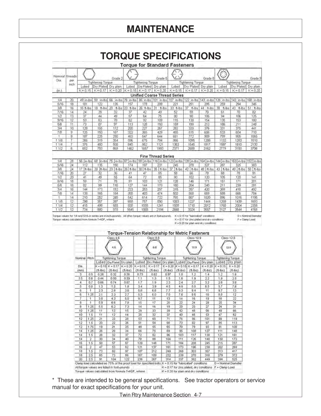
MAINTENANCE
LUBRICATION RECOMMENDATIONS
General Specification
Description
MAINTENANCE POLYCARBONATE CARE & MAINTENANCE
CLEANING THE SUPERCOAT HARD-COAT
GRAFFITI REMOVAL
RECOMMENDED FILLING INSTRUCTIONS FOR HYDRAULIC RESERVIORS
DETAILED MAINTENANCE
MAINTENANCE
REPLACEING IN-TANK HYDRAULIC FILTER
MAINTENANCE DETAILED MAINTENANCE
REPLACEING HIGH PRESSURE HYDRAULIC FILTER ELEMENT
HEAD BOWL
MAINTENANCE GREASING INNER AND OUTER DRAFT BEAM PIVOT POINTS
GREASING THE UPPER AND LOWER SHEAVES
TIGHTENING KNIFE BOLTS AND DISK BOLTS
DRIVE SHAFT YOKE, U-JOINT & STUB SHAFT
MAINTENANCE GREASING PUMP DRIVE SHAFT COUPLER
GREASING THE CASTER WHEEL SWIVEL
MAINTENANCE ADJUSTING THE CABLE LIFT
BALL VALVES
MAINTENANCE GREASING CASTER FRAME PIVOT POINTS
TIGHTENING SPINDLE BOLTS
MAINTENANCE GREASING SPINDLE
INSPECTION OF ROTARY KNIVES
ROTARY KNIFE REPLACEMENT
MAINTENANCE
Failure to follow the following warnings and instructions may result
MAINTENANCE
REPLACEMENT OF ROTARY DISK
Failure to follow the following warnings and instructions may result
serious injury or damage to the equipment or property
MAINTENANCE HEAVY DUTY SPINDLE ASSEMBLY
INSTALLATION AND BEARING ADJUSTMENT
THE SPINDLE ASSEMBLY
MAINTENANCE BEARING INSTALLATION
MAINTENANCE BEARING ADJUSTMENT
Maintenance Section
MAINTENANCE DAILY MAINTENANCE SCHEDULE
FORD TS 115-135A CAB, WOC, TWIN ROTARY
PARTS SECTION
Tiger Corporation
PARTS ORDERING GUIDE
3301 N. Louise Ave Sioux Falls, SD
Direct any questions regarding parts to
PARTS SECTION TABLE OF CONTENTS
ASSEMBLY
SECTION
Parts Section
TRACTOR MOUNT KIT - MAIN FRAME
DESCRIPTION
TRACTOR MOUNT KIT - MAIN FRAME
06700006
AVAIL
Parts Section
TRACTOR MOUNT KIT - HYDRAULICS, TRR
DESCRIPTION
TRACTOR MOUNT KIT - HYDRAULICS, TRR
MAIN FRAME - REFER TO MAIN FRAME PARTS
FRONT PUMP - REFER TO MAIN FRAME PARTS
Parts Section
TRACTOR MOUNT KIT - HYDRAULICS, TRAILKAT
DESCRIPTION
TRACTOR MOUNT KIT - HYDRAULICS, TRAILKAT
MAIN FRAME - REFER TO MAIN FRAME PARTS
FRONT PUMP - REFER TO MAIN FRAME PARTS
Parts Section
TRACTOR MOUNT KIT - BRACE/BATT, CAB/WOC
DESCRIPTION
MAIN FRAME - REFER TO MAIN FRAME PARTS
Parts Section
CABLE LIFT VALVE - 2SP, CAB/WOC
DESCRIPTION
CABLE LIFT VALVE - 2SP, CAB/WOC
Parts Section
COMBO LIFT VALVE - 2SP, CAB/WOC
DESCRIPTION
COMBO LIFT VALVE - 2SP, CAB/WOC
Parts Section
CABLE LIFT VALVE - 3SP, CAB/WOC
DESCRIPTION
CABLE LIFT VALVE - 3SP, CAB/WOC
Parts Section
COMBO LIFT VALVE - 3SP, CAB/WOC
DESCRIPTION
COMBO LIFT VALVE - 3SP, CAB/WOC
Parts Section
MIRROR BRACKET
MIRROR BRACKET
DESCRIPTION
COLLAR,CLAMP,EXHAUST,TS115A
Parts Section
HYDRAULIC COOLER ASSEMBLY, CAB
DESCRIPTION
HYDRAULIC COOLER ASSEMBLY, CAB
06510029
AVAIL
BOOM POLYCARBONATE CAB SAFETY WINDOW KIT
DESCRIPTION
POLYCARBONATE, NHTSA 115, DOOR, RH
NON-CAB STEEL CANOPY - OPTIONAL
U-BOLT,3.25x5.00x.50,20NF,GR8
DESCRIPTION
EXHAUST MOUNT
DESCRIPTION
TUBE,EXHAUST RELOCATE,TSA,6CYL
DESCRIPTION
OPTIONAL PUMP AND GRILL GUARD KIT
DESCRIPTION
BRAKE VALVE SOLENOID
DESCRIPTION
SOLENOID VALVE SWITCH AND WIRING
06510027
AVAIL
Parts Section
TWIN ROTARY COMMON SECTION
COMMON PARTS SECTION
ASSEMBLY
TABLE OF CONTENTS
SECTION
PAGE
PARTS ORDERING GUIDE
Tiger Corporation
3301 N. Louise Ave Sioux Falls, SD
Twin Rotary Common Section
REAR ROTARY DECK ASSEMBLY
DESCRIPTION
REAR ROTARY DECK ASSEMBLY
06504011
CURRENT MOTOR, M365 - 2 GEAR
NOTE ORIENTATION OF ITEM 34, LARGE ZERK FORWARD
TRAILKAT REAR ROTARY DECK ASSY
06320002
TRAILKAT REAR ROTARY DECK ASSY
Twin Rotary Common Section
REAR ROTARY CASTER WHEEL & 3PT ASSEMBLY
DESCRIPTION
REAR ROTARY CASTER WHEEL & 3PT ASSEMBLY
NOT SHOWN
BEARING, CONE, CASTER WHEEL
Twin Rotary Common Section
REAR ROTARY HYDRAULICS
DESCRIPTION
REAR ROTARY HYDRAULICS
RTRY, 60” CPLT - HP W/FBAR TRR
VALVE,BRAKE,SOL,3000PSI,METRI
Twin Rotary Common Section
60” ROTARY MOTOR
60” ROTARY MOTOR
MOTOR ASSEMBLY 2 1/4” COMPLETE TRB60
DESCRIPTION
06504016
Twin Rotary Common Section
PUMP - SERVICE PARTS
DESCRIPTION
PUMP - SERVICE PARTS
Twin Rotary Common Section
2 SP HUSCO - LOAD SENSE
DESCRIPTION
2 SP HUSCO - LOAD SENSE
Twin Rotary Common Section
2 SP HUSCO - LOAD SENSE
DESCRIPTION
2 SP HUSCO - LOAD SENSE
Twin Rotary Common Section
3 SP HUSCO - LOAD SENSE CABLE
DESCRIPTION
3 SP HUSCO - LOAD SENSE CABLE
Twin Rotary Common Section
3 SP HUSCO - LOAD SENSE COMBO
DESCRIPTION
3 SP HUSCO - LOAD SENSE COMBO
Twin Rotary Common Section
SIDE COOLER
DESCRIPTION
SIDE COOLER
DESCRIPTION
SAFETY STAND
CASTER WHEEL ASSEMBLY
DESCRIPTION
RIM, OUTER/RR RTRY CASTER ASSY
DESCRIPTION
BRAKE VALVE ASSEMBLY W/ METRI PAK
SWITCHBOX SERVICE PARTS
Twin Rotary Common Section
SWITCHBOX SCHEMATIC
Warranty Section
WARRANTY SECTION
Page
THERE ARE NO WARRANTIES WHICH EXTEND BEYOND THOSE EXPRESSED HEREIN
WARRANTY INFORMATION
SAFETY IS YOU
ONE LAST WORD
TO THE OWNER / OPERATOR / DEALER
OWNER REQUIREMENTS
OPERATOR REQUIREMENTS
Printed in USA Tiger Corporation