ASSEMBLY
SWITCH MOUNTING
Refer to the parts section for wiring diagrams. Remove top instrument panel (tach, and hour meter) for access to the wires.
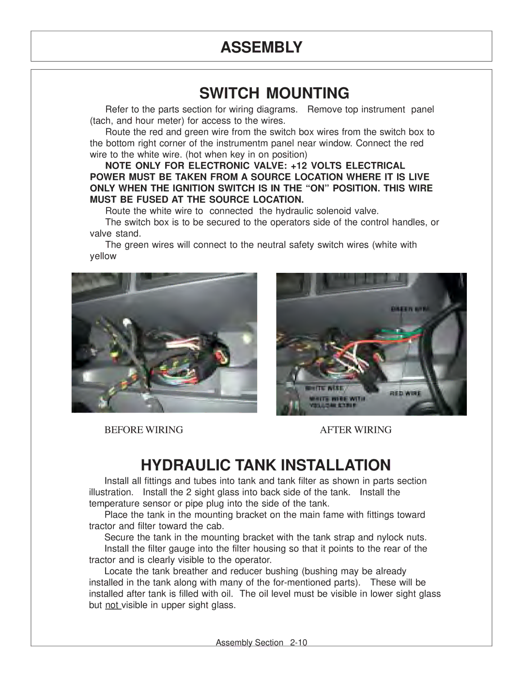
Route the red and green wire from the switch box wires from the switch box to the bottom right corner of the instrumentm panel near window. Connect the red wire to the white wire. (hot when key in on position)
NOTE ONLY FOR ELECTRONIC VALVE: +12 VOLTS ELECTRICAL POWER MUST BE TAKEN FROM A SOURCE LOCATION WHERE IT IS LIVE ONLY WHEN THE IGNITION SWITCH IS IN THE “ON” POSITION. THIS WIRE MUST BE FUSED AT THE SOURCE LOCATION.
Route the white wire to connected the hydraulic solenoid valve.
The switch box is to be secured to the operators side of the control handles, or valve stand.
The green wires will connect to the neutral safety switch wires (white with yellow
BEFORE WIRING | AFTER WIRING |
HYDRAULIC TANK INSTALLATION
Install all fittings and tubes into tank and tank filter as shown in parts section illustration. Install the 2 sight glass into back side of the tank. Install the temperature sensor or pipe plug into the side of the tank.
Place the tank in the mounting bracket on the main fame with fittings toward tractor and filter toward the cab.
Secure the tank in the mounting bracket with the tank strap and nylock nuts. Install the filter gauge into the filter housing so that it points to the rear of the
tractor and is clearly visible to the operator.
Locate the tank breather and reducer bushing (bushing may be already installed in the tank along with many of the
Assembly Section