-28 -


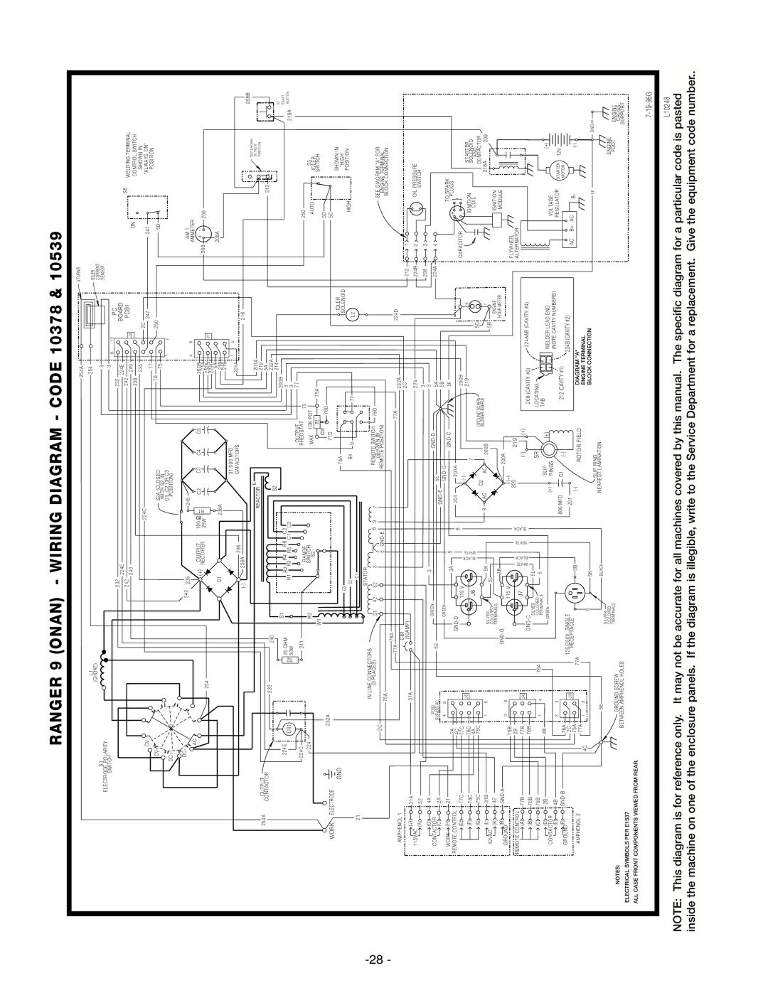
RANGER 9 (ONAN)

- WIRING DIAGRAM - CODE 10378 & 10539


254A


3 TURNS


L1


254


IDLER


(CHOKE)


S1


CURRENT


3


SENSOR


ELECTRODE POLARITY


3


SWITCH


6

12

PC


232


232


BOARD


224E


224E


S6


242


242


J2

PCB1


WELDING TERMINAL


240


240


ON


CONTROL SWITCH


236


224C


235


2C


SHOWN IN


CV-


247


"ALWAYS ON"


77


247


POSITION


CV+


S2A (CLOSED


76


250


5D


WITH S2 IN


75


DC+


C1, C2 OR C3


1

7


POSITION)


242

235


245


4

8


AM 1


AC


AMMETER


OUTPUT


(+)


100


C2


C3

C4

C5

200B


+

-


R1


208

209


254


RECTIFIER

25W


214


232A


J1


224C


D1


236A


5A


208A


216


219


31,000 MFD


201A

1

5


236A

236


CAPACITORS


216


(-)


208B


"S3" SHOWN


E


201A


REACTOR


IN "RUN"


254A


OUTPUT


219


POSITION


212


CONTACTOR


232


5A


240


S2


232A


214


S7


224E


S1


R2

R4

R6

C2


200B


START


CR1


R2

25 OHM


C3


3


216A

BUTTON


50W


R1

R3

R5

C1


3


224C


241


OUTPUT

77


RANGE


RHEOSTAT

75


250


224


W2


SWITCH


MAX

10K POT


AUTO

S5


S2


R3

75A


IDLER


W1


SWITCH


232A


CW

76D


5D


WORK

ELECTRODE


77D


5C


IDLER


SHOWN IN


GND


C3


76A


SOLENOID


"HIGH'


C2


S4

76


77


L2


HIGH

POSITION


21


C1


IN LINE CONNECTORS


STATOR


REMOTE SWITCH


(3 PLACES)

31

42

32

3


6

9


7


76D


SEE DIAGRAM "A" FOR


2C


5 GND-E


(SHOWN IN


75A


REMOTE POSITION)


ENGINE TERMINAL


76A


BLOCK CONNECTION.


77A


224D


AMPHENOL 1


77A


CB1


232A


2C


212

1


(J)


31A

(10AMP)


31A


115VAC


224


224B

2


OIL PRESSURE


(A)


32


3


208

3


SWITCH


(D)


4A


3


3


PCB2


GREEN


GND-D


CONTACTOR


5A


224A

4


5E


5E


(C)


2A


BYPASS PC


GND-E


4

8


GREEN


GND-G


5B


(H)


TO SPARK


WORK


21


GND-C


5F


2A


3A


5


+


REMOTE CONTROL


GND-D


6


201


201A


PLUGS


4C


200B


CAPACITOR


-


(E)


77C

77C


115 V


BLACK


(-)


+


(F)


76C

76C


J5


WHITE


7


219


IGNITION

STARTER


J6


SOLENOID


(G)


75C

4A


5C


COIL


AND


75C


D2


GROUND SCREW


CONTACTOR


(I)


31B


1

5


5K


9

AC

AC

200B

BLOWER BAFFLE


-


216A


209


42VAC


SILVER


(K)


42


COLORED


5L


5B


IGNITION


TERMINALS


3B


ENGINE


(B)


GND-A


GND-G


200A


HOUR METER


MODULE


3

6


GROUND


75B


115 V


(+)


FLYWHEEL


2B


BLACK


200


219


REMOTE CONTROL


J7


WHITE

BLACK

WHITE


ALTERNATOR


(A)


77B

77B


J4


(-)

(+)


GND-C


208 (CAVITY #3)


224A&B (CAVITY #4)


(B)


76B

76B


5L


SILVER


SR


LOCATING


(C)


75B


1

4

76A

COLORED

5


4B

TERMINALS


SLIP


TAB


(D)


2B


(+)


(+)


GREEN


(+)


WELDER LEAD END


VOLTAGE


CONTACTOR


RINGS


(NOTE CAVITY NUMBERS)


(E)


4B


2

4


REGULATOR

STARTER

12V


800 MFD


C1


212 (CAVITY #1)


GROUND(F)


GND-B

76A


125/250V. SINGLE


(-)


224B (CAVITY #2)


MOTOR


2C


J3


201


AC

B+

AC


RECEPTACLE


B-


75A


77A


3B


(-)


DIAGRAM "A"


(-)


AMPHENOL 2


ROTOR FIELD


4C

77A


1

3


6


ENGINE TERMINAL


5K


BLOCK CONNECTION


5F


GND-H


SLIP RING


5E


BLACK


NEAREST LAMINATION


SILVER


ENGINE


COLORED


NOTES:


GROUND SCREW

TERMINALS


FOOT

ENGINE


CROSS


ELECTRICAL SYMBOLS PER E1537


BETWEEN AMPHENOL HOLES


SUPPORT


ALL CASE FRONT COMPONENTS VIEWED FROM REAR.


7-19-96G


L10248

NOTE: This diagram is for reference only. It may not be accurate for all machines covered by this manual. The specific diagram for a particular code is pasted inside the machine on one of the enclosure panels. If the diagram is illegible, write to the Service Department for a replacement. Give the equipment code number..

Page 30
Image 30
Lincoln Electric IM511-D manual Ranger 9 Onan

IM511-D specifications

Lincoln Electric IM511-D is an innovative multi-process welding inverter designed to meet the diverse needs of modern welding applications. Renowned for its robust build quality and advanced technologies, this machine is particularly suited for professionals who require versatility and reliability on the job site.

One of the standout features of the IM511-D is its multi-process capability. This machine allows users to switch seamlessly between MIG, TIG, and Stick welding processes, making it an ideal choice for various welding tasks. Whether engaging in fabrication, repair, or maintenance, the IM511-D stands ready to tackle a wide range of metals, including carbon steel, stainless steel, and aluminum.

At the heart of the IM511-D is its inverter technology. Inverter welders are known for their efficiency and portability, and the IM511-D is no exception. The compact design makes it easy to transport without sacrificing power or performance. This inverter technology also contributes to reduced energy consumption, making it a cost-effective solution over time.

The user-friendly interface of the IM511-D enhances usability for both seasoned welders and beginners. Equipped with an intuitive digital display, the machine allows users to monitor welding parameters in real time, facilitating precise adjustments for optimal results. This ensures a smooth operation while reducing the learning curve for new users.

Another key characteristic of the IM511-D is its advanced arc control technology. This feature ensures a stable and smooth arc, reducing spatter and improving the overall quality of the weld. The machine also includes a hot start and anti-stick function in Stick welding mode, enhancing control and preventing electrode sticking—a common issue in amateur welding practices.

Additionally, the IM511-D is designed with durability in mind. Its rugged construction can withstand the rigors of industrial environments, ensuring long-lasting performance. The machine is also equipped with built-in safety features, including thermal overload protection, which helps prevent overheating during extended use.

In summary, the Lincoln Electric IM511-D combines versatility, advanced technology, and user-friendly features, making it a premier choice for professionals in the welding industry. Its multi-process capability, inverter technology, superior arc control, and robust design position it as a reliable tool for any welding task, ensuring excellent performance and quality results every time.