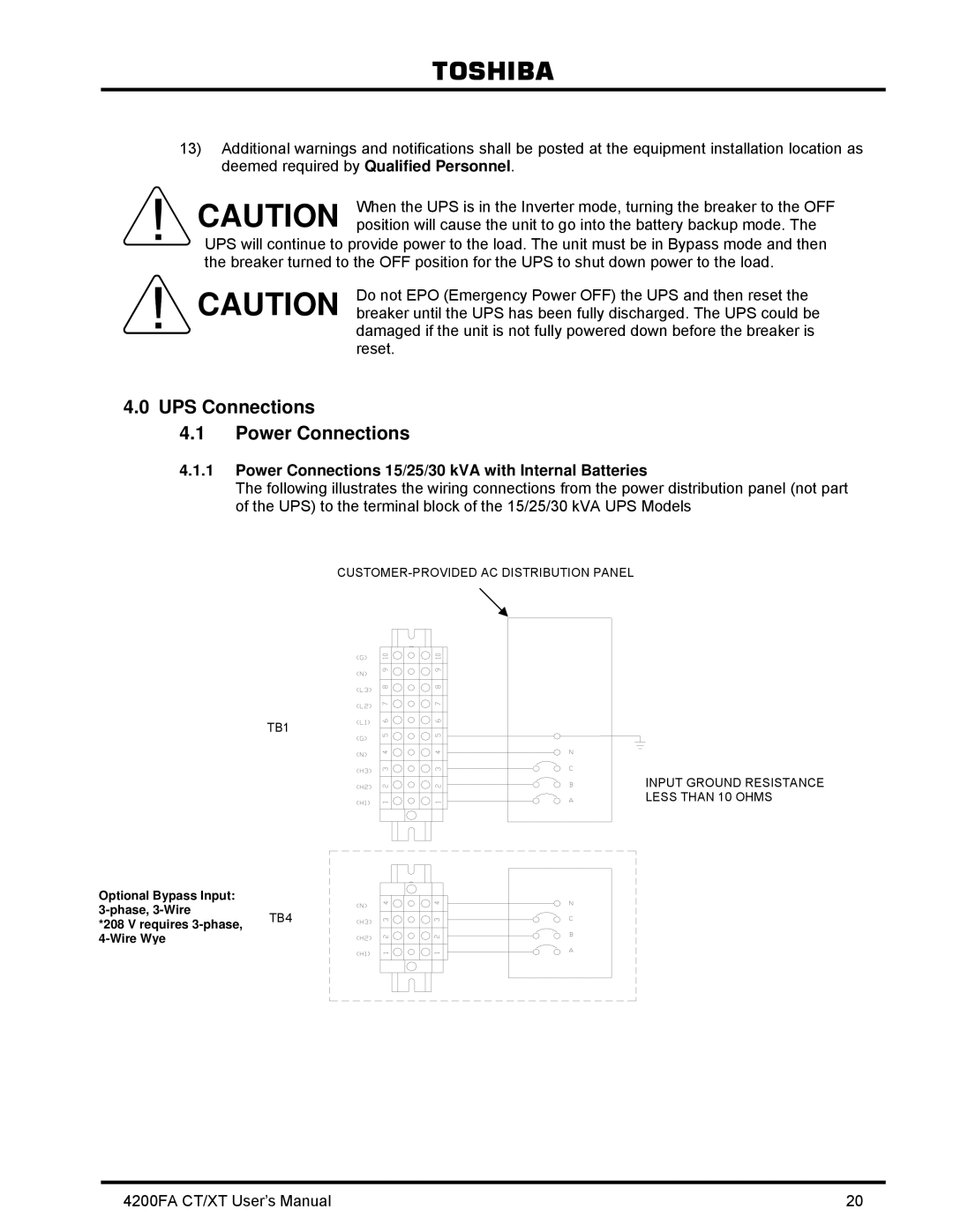
4200FA CT/XT specifications
The Toshiba 4200FA CT/XT is a noteworthy entry in the realm of advanced technology, specifically designed to cater to a variety of needs, ranging from personal computing to specialized applications. This device combines innovative features and robust specifications, making it a popular choice among professionals and tech enthusiasts alike.At the heart of the Toshiba 4200FA CT/XT lies its powerful processing unit, which ensures smooth operation across multiple applications. The device is equipped with a high-performance processor capable of handling demanding tasks, making it suitable for both casual users and those engaging in more intensive workflows. This enables the device to support multitasking effectively, allowing users to switch between applications without experiencing lag.
One of the standout features of the 4200FA CT/XT is its display. The device boasts a high-resolution screen that delivers vibrant colors and sharp imagery. This makes it ideal for media consumption, graphic design, and any task where visual fidelity is paramount. The screen also features advanced technology to enhance viewing angles and reduce glare, providing a comfortable experience in various lighting conditions.
The Toshiba 4200FA CT/XT is also designed with connectivity in mind. It comes equipped with multiple ports, including USB and HDMI options, allowing users to easily connect peripherals and external displays. Wireless connectivity options, such as Wi-Fi and Bluetooth, further enhance the device's versatility, enabling seamless integration with other devices and networks.
In terms of storage, the 4200FA CT/XT offers ample capacity to accommodate large files and applications. It utilizes advanced storage technologies that enhance data transfer speeds and reliability. This ensures that users can access their files quickly and efficiently, which is crucial for high productivity environments.
Another vital aspect of the Toshiba 4200FA CT/XT is its build quality. The device is constructed with durable materials, providing a sturdy feel while remaining lightweight for portability. This makes it a practical option for users who need to travel frequently or work in different locations.
In summary, the Toshiba 4200FA CT/XT is a feature-rich device that offers a blend of performance, versatility, and durability. Its powerful processing capabilities, high-quality display, extensive connectivity options, and reliable storage solutions make it a standout choice for a wide range of users. Whether for professional or personal use, the Toshiba 4200FA CT/XT continues to uphold Toshiba's legacy of delivering quality technology solutions.

