R160SB Basic
Introduction
Precautions
Laser Safety
Power Supply
Mains Cord
Connection to Power
Declaration of Conformity
Make your contribution to the environment
Moisture Condensation Warning
Installation Location
Accessories Supplied
Avoid the Hazards of Electrical Shock and Fire
Cleaning the Unit
Maintenance
Table of contents
Editing
Function Setup
Troubleshooting Language code Glossary Specifications
Playback
Compatibility
Features
DVD disc types
Using different disc types for different purposes
Disc Mark Specification Remarks
Choosing a disc
Introduction Choosing a disc cont’d
Disc Mark Specification Remarks DVD video
10 EN
For playback only
Standards
On DVD-R discs
On DVD-RW discs
Marks on DVD video discs
Yes
Yes No
12 EN
Discs and purposes
Front Panel
Index to parts and controls
7 8*9
14 EN
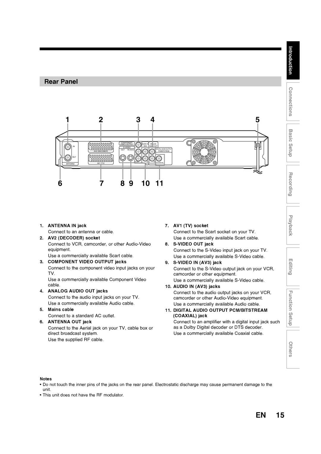
Rear Panel
Introduction Index to parts and controls cont’d
16 EN
Number buttons
Timer PROG. button
Setup button
OPEN/CLOSE a button
18 EN
Front Panel Display Guide
Display message
1Open the cover Insert batteries
Installing batteries in the remote control
About the remote control
Keep in mind the following when using the remote control
Display menu Setup menus
On Screen menu
20 EN
Format DVD-RW only
DVD-RW VR mode
Disc Protect VR mode only
CD, MP3, JPEG, Video CD
Page
Connections
24 EN
Connections
AV3RearAV4Front
Connecting to external equipment
26 EN
Digital audio for better sound quality
After you have completed connections
Basic Setup
28 EN
Initial setting
Basic Setup
Press Enter to start Channel Tuning
Channel setting
Auto tuning
Manual tuning
Move
To skip a Preset channel
Follow steps 1 to 3 in Manual tuning on
30 EN
Setting the clock
Auto Clock Setting
Manual Clock Setting
32 EN
Press Setup to exit the Clock menu
If you have a standard TV
Select TV Aspect using K / L, then press Enter
Select the desired option using K / L, then press Enter
Selecting the TV aspect ratio
Page
Recording
Information
Recording Mode
Information on DVD recording
36 EN
Making discs playable in other DVD player Finalise
What is CPRM?
Restrictions on recording
Information on copy control
Choosing the recording format of a blank disc
Select Format using K / L, then press
Selecting the Recording format
38 EN
Formatting is complete
Select Format Mode using K / L, then press Enter
Select Video mode or VR mode using K / L, then press Enter
Press Setup to exit Insert a blank disc
40 EN
Reformatting a disc Setting Auto Chapter
Recording Audio Select XP
Selecting the Sound mode
Press Setup Select Recording using K / L, then press Enter
Select PCM or Dolby Digital using K / L, then press Enter
Select External Input Audio using K / L, then press Enter
Select Stereo or Bilingual using K / L, then press Enter
42 EN
Select the recording mode using REC Mode
Basic recording
Press I/y ON/STANDBY to turn on the unit
Recording Basic recording cont’d
44 EN
Press REC I to start recording
Press Stop C to stop the recording
Has enough space remaining for the time you set
One-touch Timer Recording
46 EN
Recording One-touch Timer Recording cont’d
Timer Programming list will appear
Timer Recording
Stop mode, press Timer Prog
Select a programme using K / L, then press
48 EN
Enter the date using K / L, then press B
Enter the time to start and to end using
Recording Timer Recording cont’d
Select PDC to on or OFF using K / L. See
Select the recording mode using K / L, then press B
Press Enter when all information required is entered
50 EN
Press I/y ON/STANDBY
Press Clear to erase the selected programme
If the timer programming did not complete correctly
To correct the timer programming
Error numbers indicate
PDC Programme Delivery Control
Hints for Timer Recording
Priority of overlapped settings
52 EN
Satellite Link
If the recording time is partially overlapped
If the recording time entirely overlaps
54 EN
Connection to an external equipment
Select Select Video using K / L, then
Select the input jack type to be used using
Press Setup to exit
Before recording from external equipment, see
Recording Settings for an external equipment cont’d
56 EN
Recording from an external equipment
SEP SLP EP
Select a recording mode using REC MODE. See
58 EN
Setting disc protection
Finalising discs
Select Finalise using K / L, then press Enter
Finalising is complete
Select Yes using K / L, then press Enter
To cancel finalising DVD-RW only
60 EN
Select Auto Finalise using K / L, then press Enter
Select on using K / L, then press Enter
Auto finalise
Page
Playback
Basic playback
64 EN
Playing back a DVD-RW / DVD-R
Menu / List
Press TOP Menu to display the Title menu
Press Stop C to stop playback
Select the desired title using K / L/ / B
Select Play using K / L, then press Enter
66 EN
Playing back a DVD-VIDEO / Video CD / CD