( 3 ) PW SNR (Pulse width trigger SYNC-NON RESET)
The trigger input to CC1 of the DIGITAL terminal develops 1 frame images.
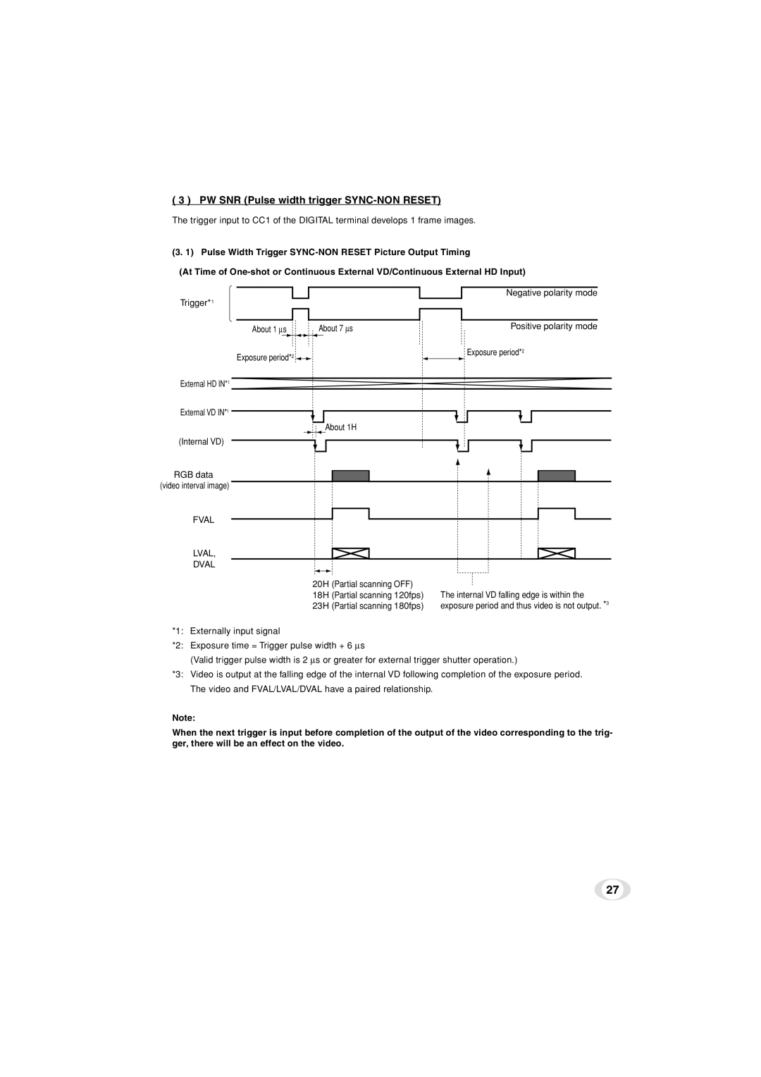
(3. 1) Pulse Width Trigger
(At Time of
Trigger*1 |
| Negative polarity mode |
|
| |
About 1 ∝s | About 7 ∝s | Positive polarity mode |
Exposure period*2 |
| Exposure period*2 |
|
|
External HD IN*1 ![]()
External VD IN*1
About 1H
(Internal VD)
RGB data (video interval image)
FVAL
LVAL,
DVAL
20H (Partial scanning OFF)
18H (Partial scanning 120fps) The internal VD falling edge is within the
23H (Partial scanning 180fps) exposure period and thus video is not output. *3
*1: Externally input signal
*2: Exposure time = Trigger pulse width + 6 ∝s
(Valid trigger pulse width is 2 ∝s or greater for external trigger shutter operation.)
*3: Video is output at the falling edge of the internal VD following completion of the exposure period. The video and FVAL/LVAL/DVAL have a paired relationship.
Note:
When the next trigger is input before completion of the output of the video corresponding to the trig- ger, there will be an effect on the video.
27