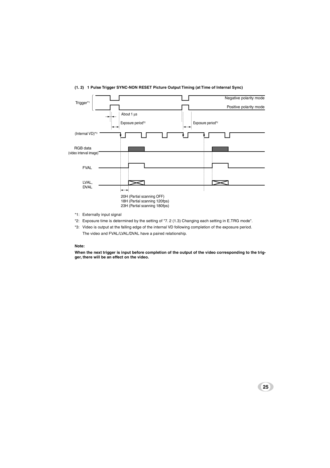
(1. 2) 1 Pulse Trigger
Negative polarity mode
Trigger*1
Positive polarity mode
About 1 ∝s
Exposure period*2 | Exposure period*2 |
(Internal VD)*3
RGB data (video interval image)
FVAL
LVAL,
DVAL
20H (Partial scanning OFF)
18H (Partial scanning 120fps)
23H (Partial scanning 180fps)
*1: Externally input signal
*2: Exposure time is determined by the setting of "7. 2 (1.3) Changing each setting in E.TRG mode".
*3: Video is output at the falling edge of the internal VD following completion of the exposure period. The video and FVAL/LVAL/DVAL have a paired relationship.
Note:
When the next trigger is input before completion of the output of the video corresponding to the trig- ger, there will be an effect on the video.
25