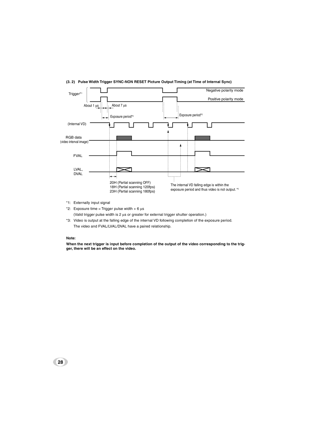
(3. 2) Pulse Width Trigger
Negative polarity mode
Trigger*1
Positive polarity mode
About 1 ∝s | About 7 ∝s |
Exposure period*2 | Exposure period*2 |
(Internal VD)
RGB data (video interval image)
FVAL
LVAL,
DVAL
20H | (Partial scanning OFF) | The internal VD falling edge is within the | |
18H | (Partial scanning 120fps) | ||
exposure period and thus video is not output. *3 | |||
23H | (Partial scanning 180fps) | ||
|
*1: Externally input signal
*2: Exposure time = Trigger pulse width + 6 ∝s
(Valid trigger pulse width is 2 ∝s or greater for external trigger shutter operation.)
*3: Video is output at the falling edge of the internal VD following completion of the exposure period.
The video and FVAL/LVAL/DVAL have a paired relationship.
Note:
When the next trigger is input before completion of the output of the video corresponding to the trig- ger, there will be an effect on the video.
28