8. INPUT OUTPUT SIGNAL SPECIFICATOINS
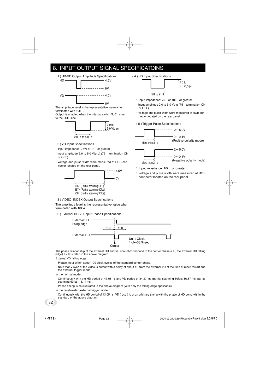
( 1 ) HD/VD Output Amplitude Specifications
HD ![]()
![]() 4.5V
4.5V
![]()
 0V
0V
VD ![]()
 4.5V
4.5V
0V
The amplitude level is the representative value when terminated with 10kΩ .
Output is enabled when the internal switch SJ01 is set to the OUT side.
( 4 ) HD Input Specifications
2.0 to
5.0
5H to 21H
* Input impedance: 75Ω or 10kΩ or greater
*Input amplitude 2.0 to 5.0
*Voltage and pulse width were measured at RGB con- nector located on the rear panel.
2.0 to
( 5 ) Trigger Pulse Specifications
5.0
2.0 µ s to 5.0 µ s
( 2 ) VD Input Specifications
* Input impedance: 75W or 1kΩ or greater |
* Input amplitude 2.0 to 5.0 |
or OFF) |
* Voltage and pulse width were measured at RGB con- |
nector located on the rear panel. |
More than 2 µ s
More than 2 µ s
2 5.0V
0 0.4V
(Positive polarity mode)
2 5.0V
0 0.4V
(Negative polarity mode)
4.5V
0V
796H (Partial scanning OFF)
387H (Partial scanning 60fps)
258H (Partial scanning 90fps)
*Input impedance: 10kΩ or greater
*Voltage and pulse width were measured at RGB connector located on the rear panel.
( 3 ) VIDEO INDEX Output Specifications
The amplitude level is the representative value when terminated with 10kW.
( 6 ) External HD/VD Input Phase Specifications
External HD rising edge
100
External HD
100
Unit : Clock
1 clk=33.9nsec
Center
The phase relationship of the external HD and VD should correspond to the center phase (i.e., the external HD falling edge) as illustrated in the above diagram.
External VD falling edge:
Please input within about 100 clock cycles of the standard center phase.
Note that V sync of the video is output with a delay of about 1H from the external VD at the time of
In the normal mode:
Continuously with the HD period of 43.05 µ s and VD period of 34.27 ms (partial scanning 60fps: 16.67 ms, partial
scanning 90fps: 11.11 ms ).
Phase timing is as illustrated in the above diagram (with only the falling edge applicable).
In the reset-restart/external trigger mode:
Continuously with the HD period of 43.05 µ s. VD (reset) is at an arbitrary timing with the phase of HD being within the standard of the above diagram.
32
Page 32 | 2004.03.24, 0:59 PMAdobe PageMaker 6.5J/PPC |