6 F 3 B 0 3 5 6
1. Introduction to S20LP
1.1 System configuration
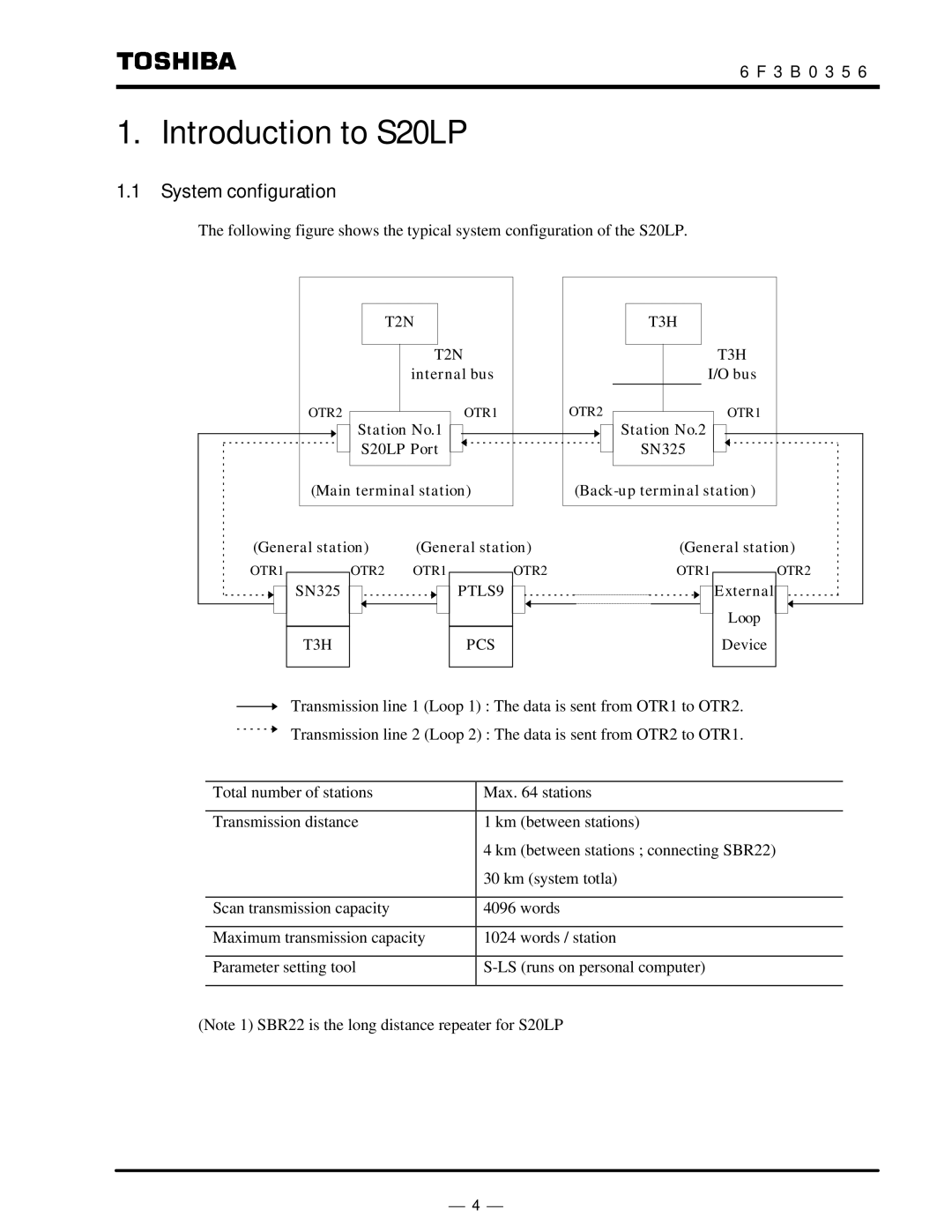
The following figure shows the typical system configuration of the S20LP.
T2N
T2N internal bus
OTR2OTR1
Station No.1
S20LP Port
(Main terminal station)
T3H
T3H
I/O bus
OTR2OTR1
![]()
![]() Station No.2
Station No.2
SN325
(General station) | (General station) | (General station) |
OTR1
SN325
T3H
OTR2 OTR1
OTR2 | OTR1 | OTR2 |
PTLS9 |
| External |
|
| Loop |
PCS |
| Device |
Transmission line 1 (Loop 1) : The data is sent from OTR1 to OTR2.
Transmission line 2 (Loop 2) : The data is sent from OTR2 to OTR1.
Total number of stations | Max. 64 stations |
|
|
Transmission distance | 1 km (between stations) |
| 4 km (between stations ; connecting SBR22) |
| 30 km (system totla) |
|
|
Scan transmission capacity | 4096 words |
|
|
Maximum transmission capacity | 1024 words / station |
|
|
Parameter setting tool | |
|
|
(Note 1) SBR22 is the long distance repeater for S20LP
⎯ 4 ⎯
