24+2G Gigabit Managed Switch User's Guide |
3.2Connecting the Switch
3.2.1 Front Panel
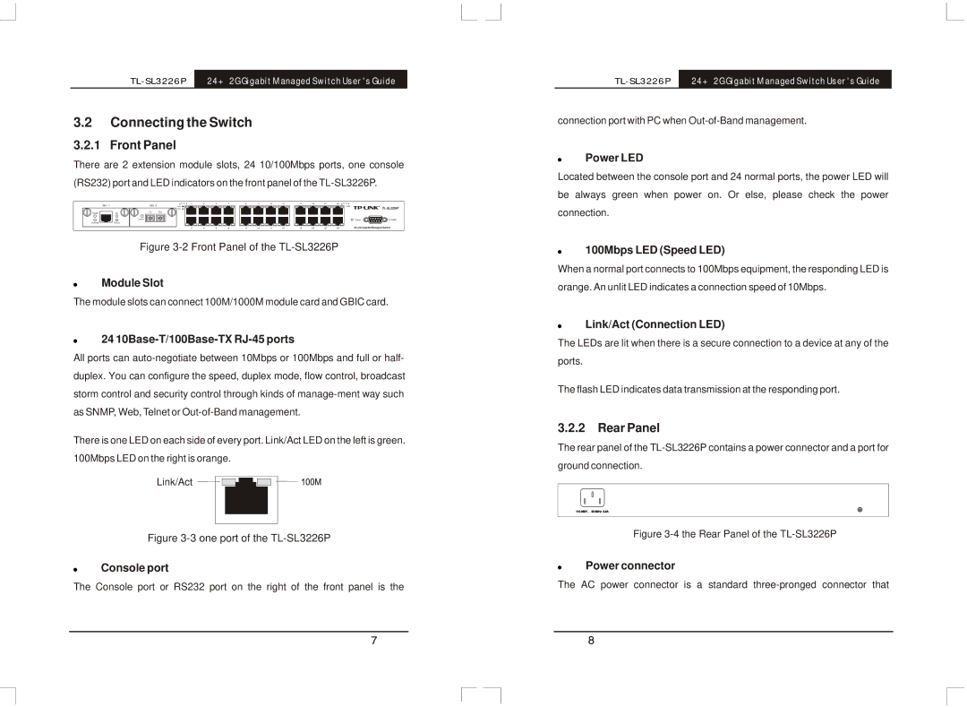
There are 2 extension module slots, 24 10/100Mbps ports, one console
(RS232) port and LED indicators on the front panel of the
Slot 1 |
| Slot 2 | 1 | 3 | 5 | 7 | 9 | 11 | 13 | 15 | 17 | 19 | 21 | 23 |
|
|
| Link |
|
|
|
|
|
|
|
|
|
|
| 100M | |||
|
|
| Act |
|
|
|
|
|
|
|
|
|
|
|
| |
1000M | Act | TX | RX |
|
|
|
|
|
|
|
|
|
|
|
|
|
|
| Link/Act |
|
|
|
|
|
|
|
|
|
|
|
| Power | Console |
10/100M | FDX/Col |
|
|
|
|
|
|
|
|
|
|
|
|
|
|
|
|
|
| 2 | 4 | 6 | 8 | 10 | 12 | 14 | 16 | 18 | 20 | 22 | 24 | 24+2G Gigabit Managed Switch | |
Figure 3-2 Front Panel of the TL-SL3226P
!Module Slot
The module slots can connect 100M/1000M module card and GBIC card.
!24 10Base-T/100Base-TX RJ-45 ports
All ports can
There is one LED on each side of every port. Link/Act LED on the left is green. 100Mbps LED on the right is orange.
Link/Act
Figure 3-3 one port of the TL-SL3226P
!Console port
The Console port or RS232 port on the right of the front panel is the
24+2G Gigabit Managed Switch User's Guide |
connection port with PC when
!Power LED
Located between the console port and 24 normal ports, the power LED will be always green when power on. Or else, please check the power connection.
!100Mbps LED (Speed LED)
When a normal port connects to 100Mbps equipment, the responding LED is orange. An unlit LED indicates a connection speed of 10Mbps.
!Link/Act (Connection LED)
The LEDs are lit when there is a secure connection to a device at any of the ports.
The flash LED indicates data transmission at the responding port.
3.2.2Rear Panel
The rear panel of the
ground connection.
Figure 3-4 the Rear Panel of the TL-SL3226P
!Power connector
The AC power connector is a standard