Installation
•Connect properly sized control wiring to the proper termination points between the zone thermostat and the unit control panel.
Condensate Drain Configuration
An evaporator condensate drain connection is provided on each unit. Refer to
Unit Dimensions for the appropriate drain location.
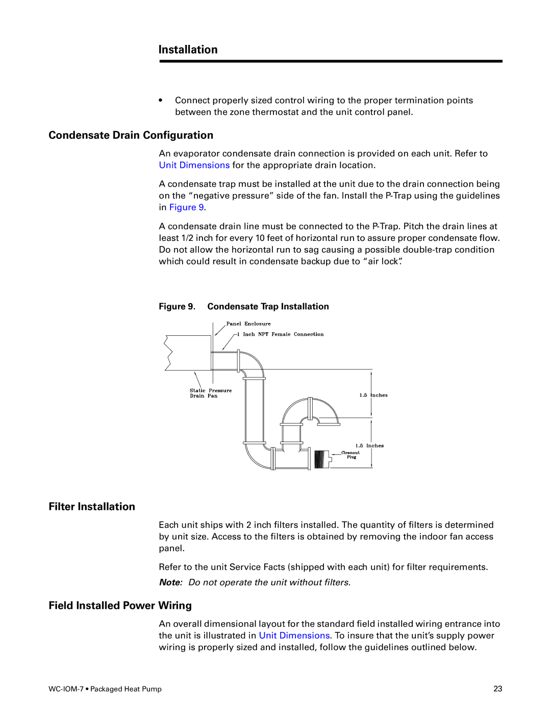
A condensate trap must be installed at the unit due to the drain connection being on the “negative pressure” side of the fan. Install the
A condensate drain line must be connected to the
Figure 9. Condensate Trap Installation
Filter Installation
Each unit ships with 2 inch filters installed. The quantity of filters is determined by unit size. Access to the filters is obtained by removing the indoor fan access panel.
Refer to the unit Service Facts (shipped with each unit) for filter requirements.
Note: Do not operate the unit without filters.
Field Installed Power Wiring
An overall dimensional layout for the standard field installed wiring entrance into the unit is illustrated in Unit Dimensions. To insure that the unit’s supply power wiring is properly sized and installed, follow the guidelines outlined below.
23 |