II. RECEIPT INSPECTION | III. INSTALLATION (continued) | |
All Traulsen products are factory tested for performance | III. b - PACKAGING (cont’d): | |
and are free from defects when shipped. The utmost | WARNING: Read and review these instructions, in their | |
care has been taken in crating this product to protect | entirety, BEFORE attempting to disassemble and remove | |
against damage in transit. All interior fittings have been | the interior bracing. If either of the diagonal or upper | |
carefully secured and the legs or casters are boxed and | ceiling braces are dropped, they could cause personal | |
strapped inside to prevent damage. Door keys will be | injury or damage to the equipment. | |
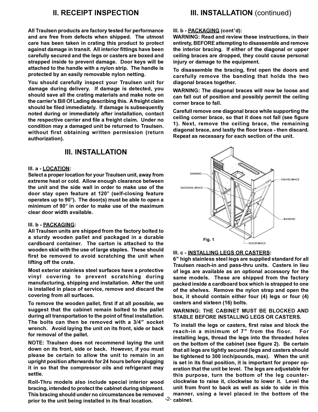
attached to the handle with a nylon strip. The handle is | To disassemble the bracing, first open the doors and | |
protected by an easily removable nylon netting. | ||
carefully remove the banding that holds the two | ||
| ||
You should carefully inspect your Traulsen unit for | diagonal braces together. | |
damage during delivery. If damage is detected, you | WARNING: The diagonal braces will now be loose and | |
should save all the crating materials and make note on | ||
can fall out of position and possibly permit the ceiling | ||
the carrier’s Bill Of Lading describing this. A freight claim | ||
corner brace to fall. | ||
should be filed immediately. If damage is subsequently | ||
Carefull remove one diagonal brace while supporting the | ||
noted during or immediately after installation, contact | ||
ceiling corner brace, so that it does not fall (see figure | ||
the respective carrier and file a freight claim. Under no | ||
1). Next, remove the ceiling brace, the remaining | ||
condition may a damaged unit be returned to Traulsen. | ||
diagonal brace, and lastly the floor brace - then discard. | ||
without first obtaining written permission (return | ||
Repeat as necessary for each section of the unit. | ||
authorization). | ||
| ||
III. INSTALLATION |
| |
III. a - LOCATION: |
| |
Select a proper location for your Traulsen unit, away from |
| |
extreme heat or cold. Allow enough clearance between |
| |
the unit and the side wall in order to make use of the |
| |
door stay open feature at 120° |
| |
operates up to 90°). The door(s) must be able to open a |
| |
minimum of 90° in order to make use of the maximum |
| |
clear door width available. |
| |
III. b - PACKAGING: |
| |
All Traulsen units are shipped from the factory bolted to |
| |
a sturdy wooden pallet and packaged in a durable | Fig. 1 | |
cardboard container. The carton is attached to the | ||
| ||
wooden skid with the use of large staples. These should | III. c - INSTALLING LEGS OR CASTERS: | |
first be removed to avoid scratching the unit when | ||
6” high stainless steel legs are supplied standard for all | ||
lifting off the crate. | ||
Traulsen | ||
Most exterior stainless steel surfaces have a protective | ||
of legs are available as an optional accessory for the | ||
vinyl covering to prevent scratching during | same models. These are shipped from the factory | |
manufacturing, shipping and installation. After the unit | packed inside a cardboard box which is strapped to one | |
is installed in place of service, remove and discard the | of the shelves. Remove the nylon strap and open the | |
covering from all surfaces. | box, it should contain either four (4) legs or four (4) | |
To remove the wooden pallet, first if at all possible, we | casters and sixteen (16) bolts. | |
suggest that the cabinet remain bolted to the pallet | WARNING: THE CABINET MUST BE BLOCKED AND | |
during all transportation to the point of final installation. | STABLE BEFORE INSTALLING LEGS OR CASTERS. | |
The bolts can then be removed with a 3/4” socket | To install the legs or casters, first raise and block the | |
wrench. Avoid laying the unit on its front, side or back | ||
for removal of the pallet. | ||
installing legs, thread the legs into the threaded holes | ||
NOTE: Traulsen does not recommend laying the unit | ||
on the bottom of the cabinet (see figure 2). Be certain | ||
down on its front, side or back. However, if you must | that all legs are tightly secured (legs and casters should | |
please be certain to allow the unit to remain in an | be tightened to 300 inch/pounds, max). When the unit | |
upright position afterwards for 24 hours before plugging | is set in its final position, it is important for proper op- | |
it in so that the compressor oils and refrigerant may | eration that the unit be level. The legs are adjustable for | |
settle. | this purpose, turn the bottom of the leg counter- | |
clockwise to raise it, clockwise to lower it. Level the | ||
bracing, intended to protect the cabinet during shipment. | unit from front to back as well as side to side in this | |
This bracing should under no circumstances be removed | manner, using a level placed in the bottom of the | |
prior to the unit being installed in its final location. |