III. INSTALLATION (continued)
III.g - INSTALLING THE CONDENSATE EVAP (cont’d): NOTE: Some models, such as single section dual- temperature refrigerator/freezers, are supplied with a
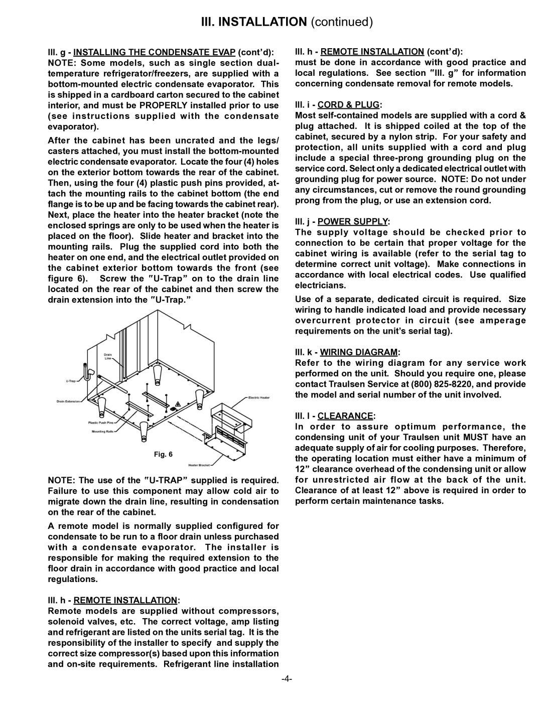
After the cabinet has been uncrated and the legs/ casters attached, you must install the
Fig. 6
NOTE: The use of the
A remote model is normally supplied configured for condensate to be run to a floor drain unless purchased with a condensate evaporator. The installer is responsible for making the required extension to the floor drain in accordance with good practice and local regulations.
III.h - REMOTE INSTALLATION:
Remote models are supplied without compressors, solenoid valves, etc. The correct voltage, amp listing and refrigerant are listed on the units serial tag. It is the responsibility of the installer to specify and supply the correct size compressor(s) based upon this information and
III.h - REMOTE INSTALLATION (cont’d):
must be done in accordance with good practice and local regulations. See section “III. g” for information concerning condensate removal for remote models.
III.i - CORD & PLUG:
Most
III.j - POWER SUPPLY:
The supply voltage should be checked prior to connection to be certain that proper voltage for the cabinet wiring is available (refer to the serial tag to determine correct unit voltage). Make connections in accordance with local electrical codes. Use qualified electricians.
Use of a separate, dedicated circuit is required. Size wiring to handle indicated load and provide necessary overcurrent protector in circuit (see amperage requirements on the unit’s serial tag).
III.k - WIRING DIAGRAM:
Refer to the wiring diagram for any service work performed on the unit. Should you require one, please contact Traulsen Service at (800)
III.l - CLEARANCE:
In order to assure optimum performance, the condensing unit of your Traulsen unit MUST have an adequate supply of air for cooling purposes. Therefore, the operating location must either have a minimum of 12” clearance overhead of the condensing unit or allow for unrestricted air flow at the back of the unit. Clearance of at least 12” above is required in order to perform certain maintenance tasks.