Connection (continued)
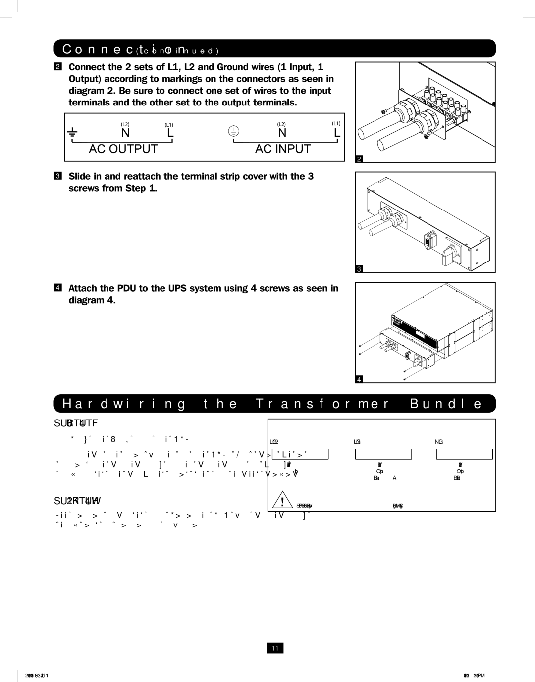
2 | Connect the 2 sets of L1, L2 and Ground wires (1 Input, 1 |
| Output) according to markings on the connectors as seen in |
| diagram 2. Be sure to connect one set of wires to the input |
| terminals and the other set to the output terminals. |
| 2 |
3 | Slide in and reattach the terminal strip cover with the 3 |
| screws from Step 1. |
3
4Attach the PDU to the UPS system using 4 screws as seen in diagram 4.
4
Hardwiring the Transformer Bundle (Input/Output)
SU6000RT4UTF
1.Plug the XFMR into the UPS.
2.Connect the transformer to the UPS. This can be a hardwire connection, outlet connection or both, provided the combined load does not exceed capacity.
SU12KRT4UHW
See manual included with Parallel PDU for connection, setup and installation information.
L1 | G | L2 | L | G | N | N | G | L | |||||
|
|
|
|
|
|
|
|
|
|
|
|
|
|
|
|
|
|
|
|
|
|
|
|
|
|
|
|
|
| 208 / 240V |
|
|
|
| 120V |
|
|
|
| 120V |
|
|
| Input |
|
|
|
| Output |
|
|
|
| Output |
|
|
|
|
|
|
|
| Branch A |
|
|
|
| Branch B |
|
Set Front Panel Selector Switch to Proper Voltage Before Making Connections
11
201207113 933070.indb 11 | 9/17/2012 1:20:01 PM |
