Tyco 4100U-S1 installation manual Wiring to IDNet Devices

Models: 4100U-S1

1 138
Download 138 pages 24.63 Kb
Page 94
Image 94

Wiring to IDNet Devices

Overview

Guidelines

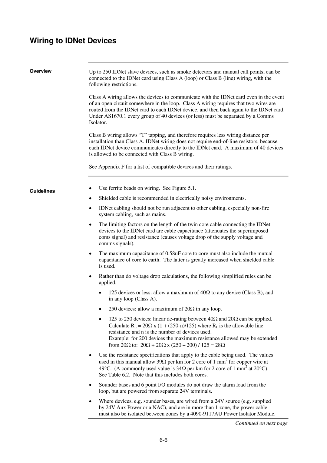
Up to 250 IDNet slave devices, such as smoke detectors and manual call points, can be connected to the IDNet card using Class A (loop) or Class B (line) wiring, with the following restrictions.

Class A wiring allows the devices to communicate with the IDNet card even in the event of an open circuit somewhere in the loop. Class A wiring requires that two wires are routed from the IDNet card to each IDNet device, and then back again to the IDNet card. Under AS1670.1 every group of 40 devices (or less) must be separated by a Comms Isolator.

Class B wiring allows “T” tapping, and therefore requires less wiring distance per installation than Class A. IDNet wiring does not require end-of-line resistors, because each IDNet device communicates directly to the IDNet card. A maximum of 40 devices is allowed to be connected with Class B wiring.

See Appendix F for a list of compatible devices and their ratings.

Use ferrite beads on wiring. See Figure 5.1.

Shielded cable is recommended in electrically noisy environments.

IDNet cabling should not be run adjacent to other cabling, especially non-fire system cabling, such as mains.

The limiting factors on the length of the twin core cable connecting the IDNet devices to the IDNet card are cable capacitance (attenuates the superimposed coms signal) and resistance (causes voltage drop of the supply voltage and comms signals).

The maximum capacitance of 0.58uF core to core must also include the mutual capacitance of core to earth. The latter is greatly increased when shielded cable is used.

Rather than do voltage drop calculations, the following simplified rules can be applied.

125 devices or less: allow a maximum of 40Ω to any device (Class B), and in any loop (Class A).

250 devices: allow a maximum of 20Ω in any loop.

125 to 250 devices: linear de-rating between 40Ω and 20Ω can be applied.

Calculate RL = 20Ω x (1 + (250-n)/125) where RL is the allowable line resistance and n is the number of devices used.

Example: for 200 devices the maximum resistance allowed may be extended

from 20Ω to: 20Ω + 20Ω x (250 – 200) / 125 = 28Ω

Use the resistance specifications that apply to the cable being used. The values used in this manual allow 39Ω per km for 2 core of 1 mm2 for copper wire at

49°C. (A commonly used value is 34Ω per km for 2 core of 1 mm2 at 20°C). See Table 6.2. Note that this includes both cores.

Sounder bases and 6 point I/O modules do not draw the alarm load from the loop, but are powered from separate 24V terminals.

Where devices, e.g. sounder bases, are wired from a 24V source (e.g. supplied by 24V Aux Power or a NAC), and are in more than 1 zone, the power cable must also be isolated between zones by a 4090-9117AU Power Isolator Module.

Continued on next page

6-6

Page 94
Image 94
Tyco 4100U-S1 installation manual Wiring to IDNet Devices

4100U-S1 specifications

The Tyco 4100U-S1 is a sophisticated and robust fire alarm control panel known for its reliability and advanced features, catering primarily to commercial and industrial applications. This system represents the latest in fire safety technology, providing comprehensive protection for a wide range of environments.

One of the main features of the Tyco 4100U-S1 is its ability to support advanced signaling protocols. This capability allows for seamless communication with a variety of initiating devices and notification appliances, ensuring a rapid response to potential fire incidents. The control panel can accommodate a significant number of devices connected through its extensive loop options, enhancing its flexibility in larger installations.

The Tyco 4100U-S1 employs Intelligent Addressable Technology, which simplifies the installation process and reduces wiring complexity. Each device on the loop can communicate its status without needing additional wiring, making it easier to troubleshoot and maintain. This feature not only enhances the system's efficiency but also helps to minimize installation costs.

Another notable characteristic of the Tyco 4100U-S1 is its user-friendly interface. The panel is designed for ease of use, featuring intuitive controls and a clear display that allows users to monitor the system’s status quickly. The graphical interface provides real-time information about the system’s performance, giving users insight into alarm conditions and system health. This accessibility aids in training personnel and encourages adherence to safety protocols.

The Tyco 4100U-S1 also boasts advanced reporting capabilities, with programmable inputs and outputs that allow for detailed event logging and alarm management. The system can be configured to send notifications via various channels, ensuring that key personnel are alerted immediately in case of an emergency. This proactive approach to fire safety helps organizations mitigate risks and enhance response strategies.

In addition, the Tyco 4100U-S1 integrates well with other building management systems, supporting various communication protocols that facilitate interoperability. This integration capability allows users to create a comprehensive safety network that addresses not only fire protection but also other critical building functions.

Overall, the Tyco 4100U-S1 stands out in the fire alarm control panel market with its combination of advanced technology, intuitive design, and extensive flexibility, making it an ideal choice for organizations seeking robust fire safety solutions. Its features and characteristics ensure that it remains a top contender in enhancing life safety and property protection.