Tyco installation manual List of Figures, Basic 4100U-S1 System

Models: 4100U-S1

1 138
Download 138 pages 24.63 Kb
Page 13
Image 13

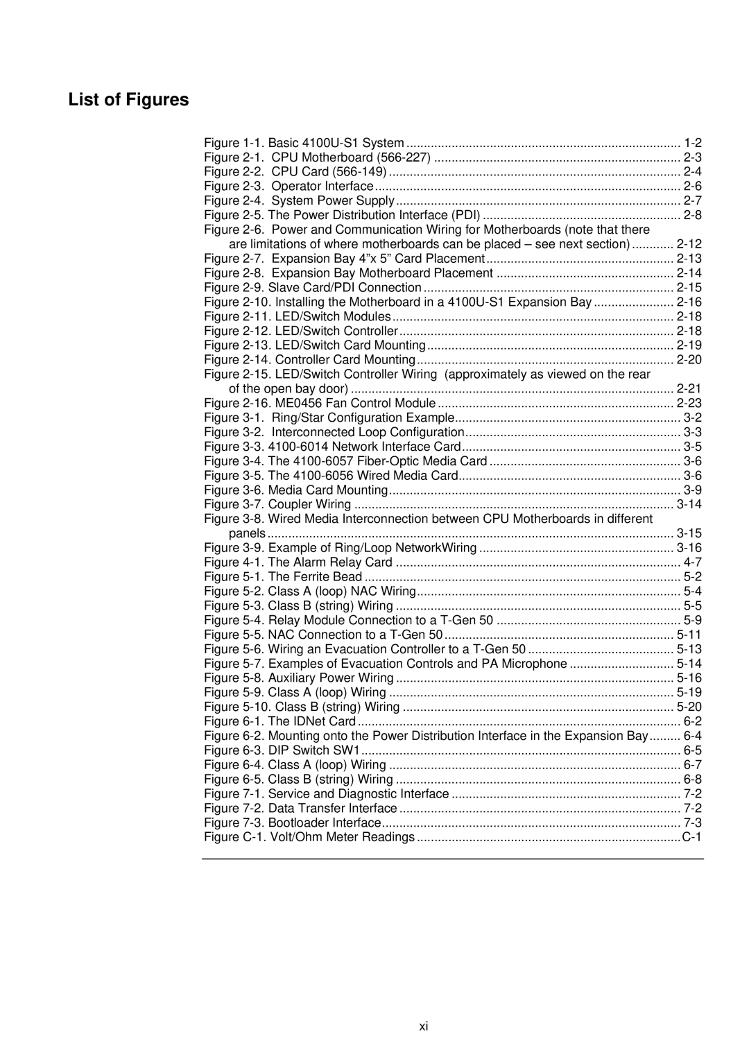
List of Figures

Figure 1-1. Basic 4100U-S1 System

1-2

Figure 2-1. CPU Motherboard (566-227)

2-3

Figure 2-2. CPU Card (566-149)

2-4

Figure 2-3.

Operator Interface

2-6

Figure 2-4. System Power Supply

2-7

Figure 2-5. The Power Distribution Interface (PDI)

2-8

Figure 2-6. Power and Communication Wiring for Motherboards (note that there

2-12

are limitations of where motherboards can be placed – see next section)

Figure 2-7. Expansion Bay 4”x 5” Card Placement

2-13

Figure 2-8. Expansion Bay Motherboard Placement

2-14

Figure 2-9. Slave Card/PDI Connection

2-15

Figure 2-10. Installing the Motherboard in a 4100U-S1 Expansion Bay

2-16

Figure 2-11. LED/Switch Modules

2-18

Figure 2-12. LED/Switch Controller

2-18

Figure 2-13. LED/Switch Card Mounting

2-19

Figure 2-14. Controller Card Mounting

2-20

Figure 2-15. LED/Switch Controller Wiring (approximately as viewed on the rear

2-21

of the open bay door)

Figure 2-16. ME0456 Fan Control Module

2-23

Figure 3-1.

Ring/Star Configuration Example

3-2

Figure 3-2.

Interconnected Loop Configuration

3-3

Figure 3-3.4100-6014 Network Interface Card

3-5

Figure 3-4. The 4100-6057Fiber-Optic Media Card

3-6

Figure 3-5. The 4100-6056 Wired Media Card

3-6

Figure 3-6. Media Card Mounting

3-9

Figure 3-7. Coupler Wiring

3-14

Figure 3-8. Wired Media Interconnection between CPU Motherboards in different

3-15

panels

.....................................................................................................................

Figure 3-9. Example of Ring/Loop NetworkWiring

3-16

Figure 4-1. The Alarm Relay Card

4-7

Figure 5-1. The Ferrite Bead

5-2

Figure 5-2. Class A (loop) NAC Wiring

5-4

Figure 5-3. Class B (string) Wiring

5-5

Figure 5-4. Relay Module Connection to a T-Gen 50

5-9

Figure 5-5. NAC Connection to a T-Gen 50

5-11

Figure 5-6. Wiring an Evacuation Controller to a T-Gen 50

5-13

Figure 5-7. Examples of Evacuation Controls and PA Microphone

5-14

Figure 5-8. Auxiliary Power Wiring

5-16

Figure 5-9. Class A (loop) Wiring

5-19

Figure 5-10. Class B (string) Wiring

5-20

Figure 6-1. The IDNet Card

6-2

Figure 6-2. Mounting onto the Power Distribution Interface in the Expansion Bay

6-4

Figure 6-3. DIP Switch SW1

6-5

Figure 6-4. Class A (loop) Wiring

6-7

Figure 6-5. Class B (string) Wiring

6-8

Figure 7-1. Service and Diagnostic Interface

7-2

Figure 7-2. Data Transfer Interface

7-2

Figure 7-3. Bootloader Interface

7-3

Figure C-1. Volt/Ohm Meter Readings

C-1

xi

Page 13
Image 13
Tyco installation manual List of Figures, Basic 4100U-S1 System

4100U-S1 specifications

The Tyco 4100U-S1 is a sophisticated and robust fire alarm control panel known for its reliability and advanced features, catering primarily to commercial and industrial applications. This system represents the latest in fire safety technology, providing comprehensive protection for a wide range of environments.

One of the main features of the Tyco 4100U-S1 is its ability to support advanced signaling protocols. This capability allows for seamless communication with a variety of initiating devices and notification appliances, ensuring a rapid response to potential fire incidents. The control panel can accommodate a significant number of devices connected through its extensive loop options, enhancing its flexibility in larger installations.

The Tyco 4100U-S1 employs Intelligent Addressable Technology, which simplifies the installation process and reduces wiring complexity. Each device on the loop can communicate its status without needing additional wiring, making it easier to troubleshoot and maintain. This feature not only enhances the system's efficiency but also helps to minimize installation costs.

Another notable characteristic of the Tyco 4100U-S1 is its user-friendly interface. The panel is designed for ease of use, featuring intuitive controls and a clear display that allows users to monitor the system’s status quickly. The graphical interface provides real-time information about the system’s performance, giving users insight into alarm conditions and system health. This accessibility aids in training personnel and encourages adherence to safety protocols.

The Tyco 4100U-S1 also boasts advanced reporting capabilities, with programmable inputs and outputs that allow for detailed event logging and alarm management. The system can be configured to send notifications via various channels, ensuring that key personnel are alerted immediately in case of an emergency. This proactive approach to fire safety helps organizations mitigate risks and enhance response strategies.

In addition, the Tyco 4100U-S1 integrates well with other building management systems, supporting various communication protocols that facilitate interoperability. This integration capability allows users to create a comprehensive safety network that addresses not only fire protection but also other critical building functions.

Overall, the Tyco 4100U-S1 stands out in the fire alarm control panel market with its combination of advanced technology, intuitive design, and extensive flexibility, making it an ideal choice for organizations seeking robust fire safety solutions. Its features and characteristics ensure that it remains a top contender in enhancing life safety and property protection.