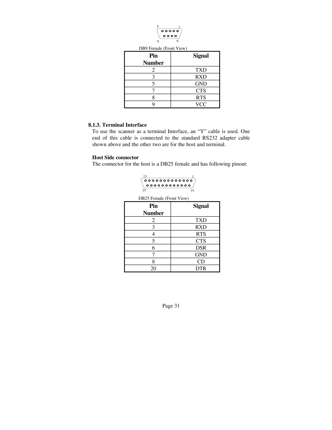
5 | 1 |
9 | 6 |
DB9 Female (Front View) | |
Pin | Signal |
Number |
|
2 | TXD |
3 | RXD |
5 | GND |
7 | CTS |
8 | RTS |
9 | VCC |
8.1.3. Terminal Interface
To use the scanner as a terminal Interface, an “Y” cable is used. One end of this cable is connected to the standard RS232 adapter cable shown above and the other two are for the host and terminal.
Host Side connector
The connector for the host is a DB25 female and has following pinout:
13 | 1 |
25 | 14 |
DB25 Female (Front View) |
|
Pin | Signal |
Number |
|
2 | TXD |
3 | RXD |
4 | RTS |
5 | CTS |
6 | DSR |
7 | GND |
8 | CD |
20 | DTR |
Page 31
