Rear Panel and Connector Diagrams | Instrument Overview | |||||||
Table |
|
| ||||||
|
|
|
|
| ||||
Index | Name/Image | Description |
| Connector | ||||
|
|
|
|
|
|
|
| |
|
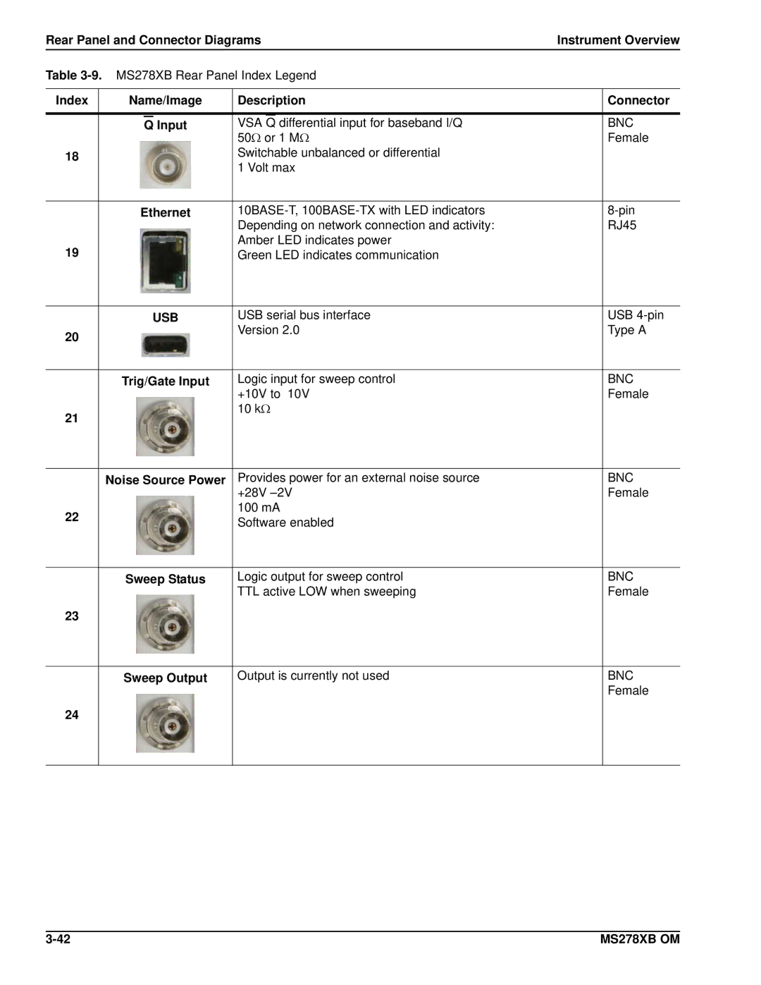
| Q | Input | VSA | Q | differential input for baseband I/Q |
| BNC |
|
|
|
| 50Ω or 1 MΩ |
| Female | ||
18 |
|
|
| Switchable unbalanced or differential |
|
| ||
|
|
|
| 1 Volt max |
|
| ||
|
|
|
|
| ||||
| Ethernet |
| ||||||
|
|
|
| Depending on network connection and activity: |
| RJ45 | ||
19 |
|
|
| Amber LED indicates power |
|
| ||
|
|
| Green LED indicates communication |
|
| |||
|
|
|
|
|
| |||
|
| USB | USB serial bus interface |
| USB | |||
20 |
|
|
| Version 2.0 |
| Type A | ||
|
|
|
|
|
|
|
| |
|
|
|
|
| ||||
| Trig/Gate Input | Logic input for sweep control |
| BNC | ||||
|
|
|
| +10V to |
| Female | ||
21 |
|
|
| 10 kΩ |
|
| ||
|
|
|
|
|
|
|
| |
|
|
|
|
| ||||
| Noise Source Power | Provides power for an external noise source |
| BNC | ||||
|
|
|
| +28V ±2V |
| Female | ||
22 |
|
|
| 100 mA |
|
| ||
|
|
| Software enabled |
|
| |||
|
|
|
|
|
| |||
|
|
|
|
| ||||
| Sweep Status | Logic output for sweep control |
| BNC | ||||
|
|
|
| TTL active LOW when sweeping |
| Female | ||
23 |
|
|
|
|
|
|
|
|
|
|
|
|
| ||||
| Sweep Output | Output is currently not used |
| BNC | ||||
|
|
|
|
|
|
|
| Female |
24 |
|
|
|
|
|
|
|
|
|
|
|
|
|
|
|
|
|
MS278XB OM |
