Measurements | Operation Verification |
Reference Level Switching Uncertainty
The following test can be used to verify that the MS2781B is within its Reference Level Switching Uncertainty specifications.
Test Setup
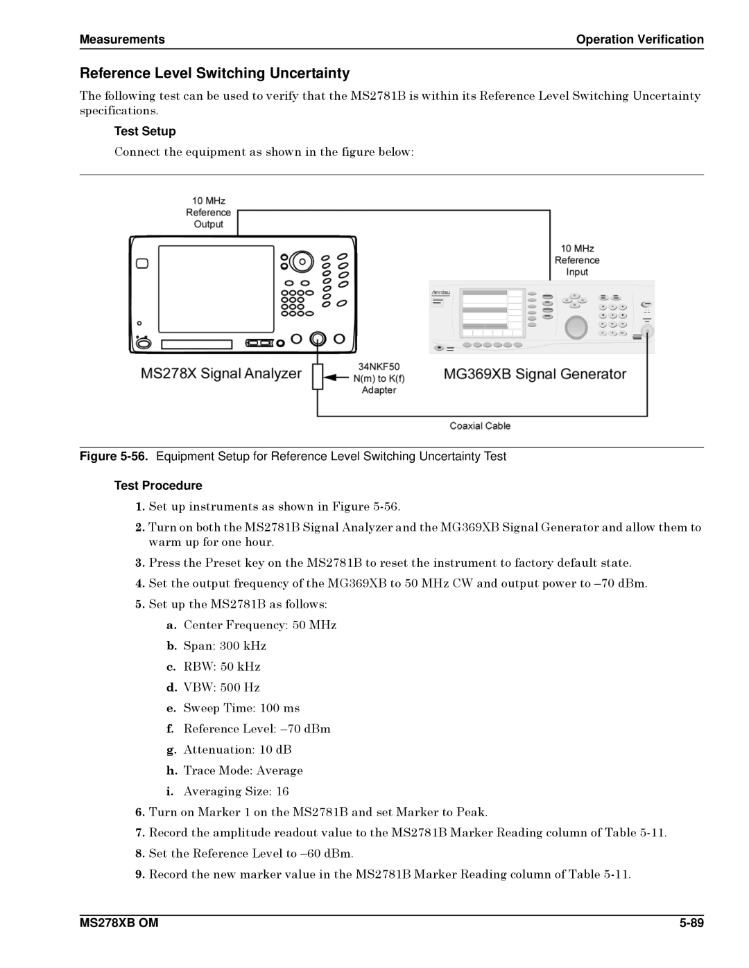
Connect the equipment as shown in the figure below:
Figure 5-56. Equipment Setup for Reference Level Switching Uncertainty Test
Test Procedure
1.Set up instruments as shown in Figure
2.Turn on both the MS2781B Signal Analyzer and the MG369XB Signal Generator and allow them to warm up for one hour.
3.Press the Preset key on the MS2781B to reset the instrument to factory default state.
4.Set the output frequency of the MG369XB to 50 MHz CW and output power to
5.Set up the MS2781B as follows:
a.Center Frequency: 50 MHz
b.Span: 300 kHz
c.RBW: 50 kHz
d.VBW: 500 Hz
e.Sweep Time: 100 ms
f.Reference Level:
g.Attenuation: 10 dB
h.Trace Mode: Average
i.Averaging Size: 16
6.Turn on Marker 1 on the MS2781B and set Marker to Peak.
7.Record the amplitude readout value to the MS2781B Marker Reading column of Table
8.Set the Reference Level to
9.Record the new marker value in the MS2781B Marker Reading column of Table
MS278XB OM |
