Operation Verification | Measurements |
9.Adjust the MG369XB RF output so that the power meter input B reading is
Note: Set the Cal Factor on the power meter to match the frequency being measured.
10.Repeat steps 7 and 8 for the other frequencies listed in Table
11.Disconnect the Phase Matched
12.Set up the MS2781B as follows:
a.Center Frequency: 50 MHz
b.Span: 300 kHz
c.RBW:50 kHz
d.VBW: 500 Hz
e.Sweep Time: 100 ms
f.Attenuation: 10 dB
g.Reference Level: 0 dBm
13.Set the frequency on the MG369XB to 50 MHz, then set the output power level so that the sensor A reading matches the corresponding value as recorded in column 2 of Table
14.Set the Marker to Peak. Record the measured Marker value in Table
15.Repeat steps 11 and 12. Record the measured results in Table
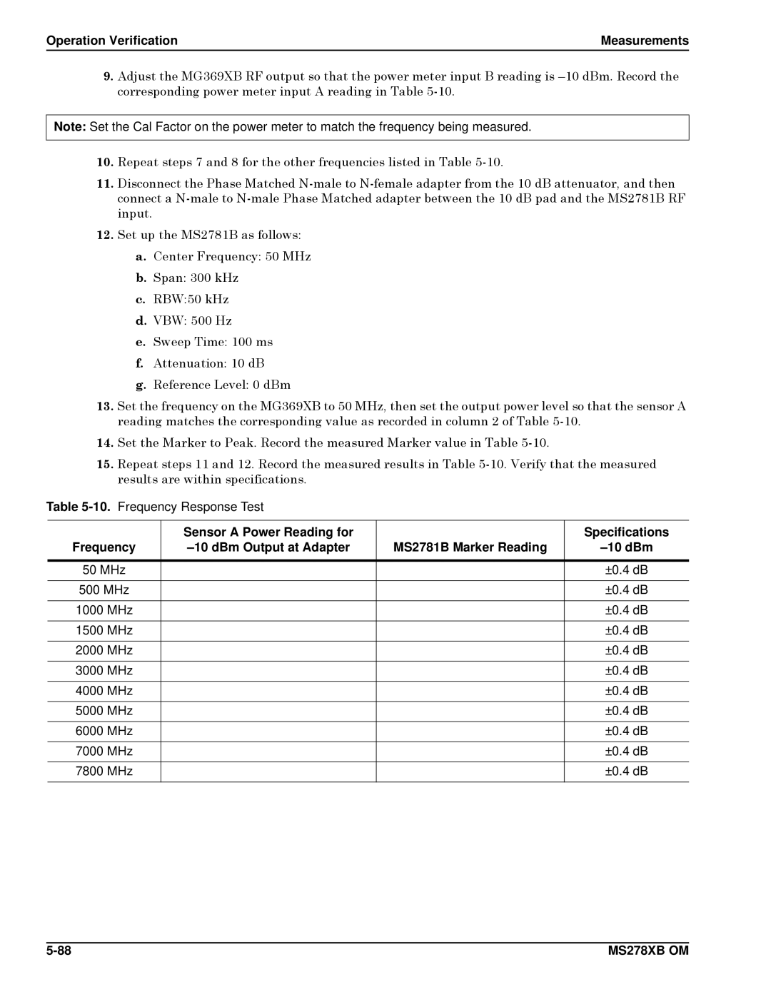
Table 5-10. Frequency Response Test
| Sensor A Power Reading for |
| Specifications |
Frequency | MS2781B Marker Reading | ||
|
|
|
|
50 MHz |
|
| ±0.4 dB |
|
|
|
|
500 MHz |
|
| ±0.4 dB |
|
|
|
|
1000 MHz |
|
| ±0.4 dB |
|
|
|
|
1500 MHz |
|
| ±0.4 dB |
|
|
|
|
2000 MHz |
|
| ±0.4 dB |
|
|
|
|
3000 MHz |
|
| ±0.4 dB |
|
|
|
|
4000 MHz |
|
| ±0.4 dB |
|
|
|
|
5000 MHz |
|
| ±0.4 dB |
|
|
|
|
6000 MHz |
|
| ±0.4 dB |
|
|
|
|
7000 MHz |
|
| ±0.4 dB |
|
|
|
|
7800 MHz |
|
| ±0.4 dB |
|
|
|
|
MS278XB OM |