DV360/580 Series Direct Vent Gas Fireplace

High Elevations

Input ratings are shown in BTU per hour and are certified without deration for elevations up to 4,500 feet (1,370m) above sea level.

For elevations above 4,500 feet (1,370m) in USA, installations must be in accordance with the current ANSI Z223.1/NFPA 54 and/or local codes having jurisdiction.

In Canada, please consult provincial and/or local authorities having jurisdiction for installations at elevations above 4,500 feet (1,370m).

Gas Line Installation

When purging gas line the front glass must be removed.

The gas pipeline can be brought in through the right side of the appliance. Knockouts are provided at conve- nient locations to allow for the gas pipe installation and testing of any gas connection.

The gas line connection can be made with properly tinned 3/8” copper tubing, 1/2” rigid pipe or an approved flex connector. Since some municipalities have addi- tional local codes, it is always best to consult your local authority and the CSA-B149.1installation codes.

For USA installations consult the current National Fuel Gas Code, ANSI Z223.1/NFPA 54.

1/2” Gas Supply

1/2” NPT x 3/8” Flare Shut- off Valve

3/8” Flex Line (from valve)

FP297a

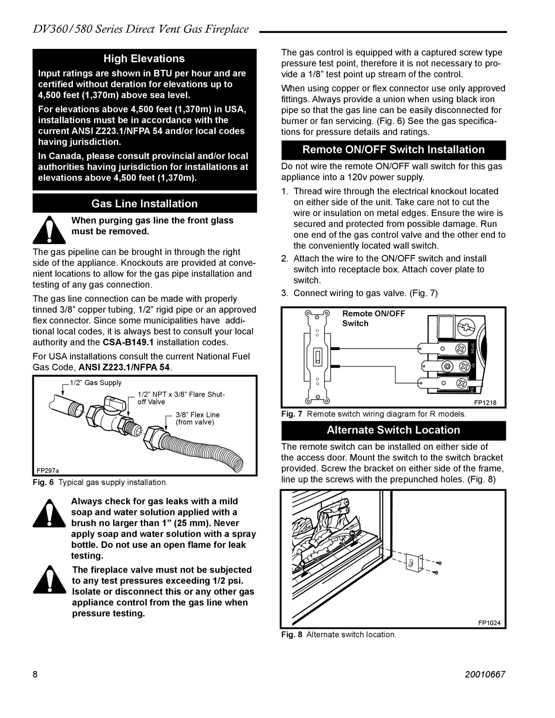
Fig. 6 Typical gas supply installation.

Always check for gas leaks with a mild soap and water solution applied with a brush no larger than 1” (25 mm). Never apply soap and water solution with a spray bottle. Do not use an open flame for leak testing.

The fireplace valve must not be subjected to any test pressures exceeding 1/2 psi. Isolate or disconnect this or any other gas appliance control from the gas line when pressure testing.

The gas control is equipped with a captured screw type pressure test point, therefore it is not necessary to pro- vide a 1/8” test point up stream of the control.

When using copper or flex connector use only approved fittings. Always provide a union when using black iron pipe so that the gas line can be easily disconnected for burner or fan servicing. (Fig. 6) See the gas specifica- tions for pressure details and ratings.

Remote ON/OFF Switch Installation

Do not wire the remote ON/OFF wall switch for this gas appliance into a 120v power supply.

1.Thread wire through the electrical knockout located on either side of the unit. Take care not to cut the wire or insulation on metal edges. Ensure the wire is secured and protected from possible damage. Run one end of the gas control valve and the other end to the conveniently located wall switch.

2.Attach the wire to the ON/OFF switch and install switch into receptacle box. Attach cover plate to switch.

3.Connect wiring to gas valve. (Fig. 7)


Remote ON/OFF


Switch


TPTH


TP


TH


FP1218

Fig. 7

Remote switch wiring diagram for R models.

Alternate Switch Location

The remote switch can be installed on either side of the access door. Mount the switch to the switch bracket provided. Screw the bracket on either side of the frame, line up the screws with the prepunched holes. (Fig. 8)

FP1024

Fig. 8 Alternate switch location.

8

20010667

Page 8
Image 8
Vermont Casting DV360 High Elevations, Gas Line Installation, Remote ON/OFF Switch Installation, Alternate Switch Location

DV580, DV360, DV360 specifications

Vermont Castings is a name synonymous with quality and craftsmanship in the world of fireplaces. Among their celebrated products, the DV580, DV360, and DV360 stand out for their advanced technology, efficiency, and aesthetic appeal. Each of these models offers unique features designed to enhance home heating while maintaining a focus on environmental responsibility.

The DV580 is a powerful direct vent gas stove that seamlessly combines traditional aesthetics with modern functionality. With its large viewing window, it creates a cozy ambiance while allowing users to enjoy the mesmerizing flames. One of its main features is the advanced burner system, which provides a realistic flame appearance. This model also boasts an impressive BTU output, allowing it to heat larger spaces efficiently. The unit is equipped with an electronic ignition, ensuring reliable start-ups even in cold weather.

The DV360, a slightly smaller but equally efficient model, offers versatility for various home settings. With its compact design, it can fit into tighter spaces without sacrificing heating capacity. The DV360 features a unique dual burner system, which promotes a more even and consistent flame. Its direct vent technology ensures that all combustion byproducts are vented outside, maintaining indoor air quality. This model also includes an adjustable flame height, giving users control over the intensity of the heat and ambiance.

In addition to performance, both the DV580 and DV360 prioritize energy efficiency. They are designed to operate with minimal emissions, making them an environmentally friendly choice for homeowners. With a variety of finish options and customizable face designs, these models can complement any home decor. Another key characteristic is the straightforward installation process, which allows homeowners the benefit of having their unit up and running in no time.

Overall, the Vermont Castings DV580, DV360, and DV360 models exemplify a harmonious blend of innovation, functionality, and style. They not only provide warmth but also contribute to the overall aesthetic of any space. With their commitment to quality and performance, Vermont Castings continues to set the standard for direct vent gas stoves, ensuring customers enjoy the best of both worlds: comfort and beauty in their homes.