DVRT41Direct Vent Gas Fireplace

Optional Accessories Available

Fan Kits

FK12 Fan Assembly

1.Open louvre assembly bottom.

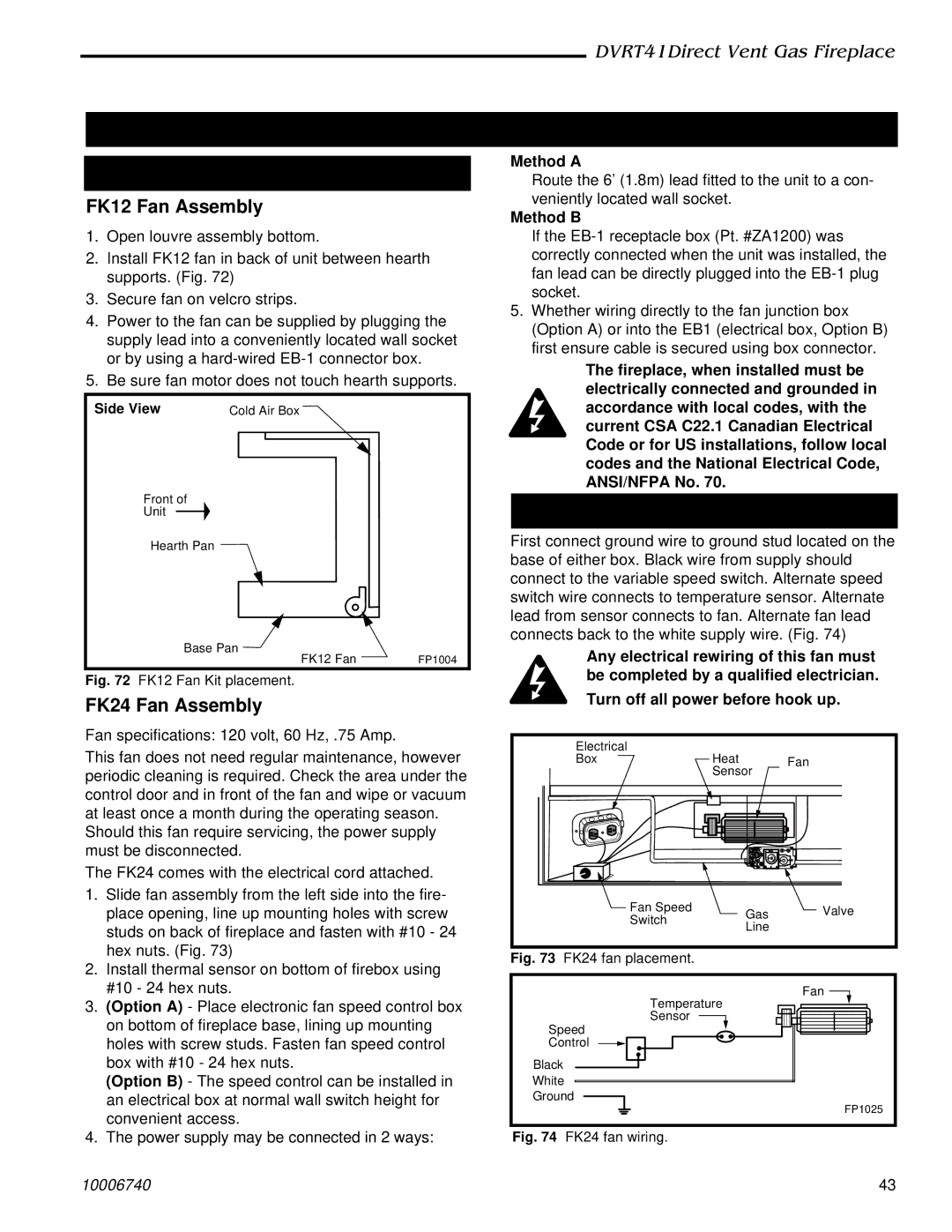
2.Install FK12 fan in back of unit between hearth supports. (Fig. 72)

3.Secure fan on velcro strips.

4.Power to the fan can be supplied by plugging the supply lead into a conveniently located wall socket or by using a hard-wired EB-1 connector box.

5.Be sure fan motor does not touch hearth supports.

Side View

Cold Air Box

Front of

Unit

Hearth Pan

Base Pan

FK12 Fan

FP1004

Fig. 72 FK12 Fan Kit placement.

FK24 Fan Assembly

Fan specifications: 120 volt, 60 Hz, .75 Amp.

This fan does not need regular maintenance, however periodic cleaning is required. Check the area under the control door and in front of the fan and wipe or vacuum at least once a month during the operating season.

Should this fan require servicing, the power supply must be disconnected.

The FK24 comes with the electrical cord attached.

1.Slide fan assembly from the left side into the fire- place opening, line up mounting holes with screw studs on back of fireplace and fasten with #10 - 24 hex nuts. (Fig. 73)

2.Install thermal sensor on bottom of firebox using #10 - 24 hex nuts.

3.(Option A) - Place electronic fan speed control box on bottom of fireplace base, lining up mounting holes with screw studs. Fasten fan speed control box with #10 - 24 hex nuts.

(Option B) - The speed control can be installed in an electrical box at normal wall switch height for convenient access.

4.The power supply may be connected in 2 ways:

Method A

Route the 6’ (1.8m) lead fitted to the unit to a con- veniently located wall socket.

Method B

If the EB-1 receptacle box (Pt. #ZA1200) was correctly connected when the unit was installed, the fan lead can be directly plugged into the EB-1 plug socket.

5.Whether wiring directly to the fan junction box (Option A) or into the EB1 (electrical box, Option B) first ensure cable is secured using box connector.

The fireplace, when installed must be electrically connected and grounded in accordance with local codes, with the current CSA C22.1 Canadian Electrical Code or for US installations, follow local codes and the National Electrical Code, ANSI/NFPA No. 70.

Hard (Direct) Wire Hook Up

First connect ground wire to ground stud located on the base of either box. Black wire from supply should connect to the variable speed switch. Alternate speed switch wire connects to temperature sensor. Alternate lead from sensor connects to fan. Alternate fan lead connects back to the white supply wire. (Fig. 74)

Any electrical rewiring of this fan must be completed by a qualified electrician.

Turn off all power before hook up.


Electrical

Heat


Box

Fan


Sensor


F

P


TO


Fan Speed

Gas

Valve


Switch

Line


Fig. 73

FK24 fan placement.


Fan

Temperature

Sensor

Speed

Control

Black

White

Ground

FP1025

Fig. 74 FK24 fan wiring.

10006740

43

Page 43
Image 43
Vermont Casting DVRT41 manual Optional Accessories Available, Fan Kits, FK12 Fan Assembly, FK24 Fan Assembly

DVRT41 specifications

The Vermont Casting DVRT41 is a remarkable gas fireplace that harmoniously combines contemporary aesthetics with advanced heating technology. Designed to enhance any living space, the DVRT41 stands out with its impressive features and functionality, making it a popular choice for those looking to elevate their home environment.

One of the most notable features of the DVRT41 is its efficient heat output. With an impressive BTU range, this fireplace can warm spaces effectively while maintaining low emissions. This efficiency is complemented by Vermont Castings' commitment to sustainability, ensuring that the DVRT41 aligns with environmental considerations.

Aesthetically, the DVRT41 offers a customizable experience. Consumers can choose from various faceplate designs, glass door styles, and finishes to match any décor. The fireplace’s large viewing area provides an unobstructed view of the flames, creating a cozy atmosphere that’s perfect for gatherings or quiet evenings.

The DVRT41 incorporates advanced technologies aimed at maximizing user experience. The fireplace features an intuitive remote control for convenience, allowing users to adjust flame height and heat output easily. This adaptability ensures that homeowners can create the perfect ambiance at any time. The ignition system is designed for reliability and ease, ensuring that starting the fireplace is hassle-free, even in challenging conditions.

Safety is a top priority with the DVRT41. The unit includes features such as a safety shut-off system and a tempered glass front to prevent accidental burns. Additionally, the design allows for efficient venting, minimizing the risk of backdraft or buildup of harmful gases.

Maintenance is straightforward, thanks to the unit's design. The DVRT41 is constructed with durable materials that resist corrosion and wear, ensuring longevity and reduced upkeep costs. Regular cleaning is simple, ensuring that the fireplace remains functional and beautiful for years to come.

Overall, the Vermont Casting DVRT41 gas fireplace is not only a source of warmth but also a stunning focal point within any home. Its blend of efficiency, safety, and design flexibility make it a top choice for homeowners seeking an effective heating solution that doesn’t compromise on style or substance. The DVRT41 exemplifies Vermont Castings' commitment to quality, ensuring that every unit delivers exceptional performance and aesthetic appeal.