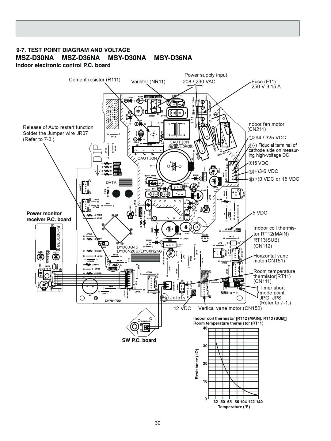
9-7. TEST POINT DIAGRAM AND VOLTAGE
Indoor electronic control P.C. board
Cement resistor (R111) |
| Power supply input |
Varistor (NR11) | 208 / 230 VAC | |
|
| } |
Fuse (F11) 250 V 3.15 A
Release of Auto restart function Solder the Jumper wire JR07 (Refer to
Power monitor receiver P.C. board
Indoor fan motor (CN211)
![]() 294 / 325 VDC
294 / 325 VDC
![]() 15 VDC
15 VDC
![]() (+)3-6
(+)3-6
![]()
![]() (+)0 VDC or 15 VDC
(+)0 VDC or 15 VDC
5 VDC
Indoor coil thermis- tor RT12(MAIN) RT13(SUB) (CN112)
Horizontal vane motor(CN151)
Room temperature
thermistor(RT11)
(CN111)
![]()
![]() }Timer short
}Timer short
mode point
JPG, JPS (Refer to
12 VDC Vertical vane motor (CN152)
Indoor coil thermistor [RT12 (MAIN), RT13 (SUB)] Room temperature thermistor (RT11)
40
SW P.C. board
Resistance (kΩ)
30
20
10
0 | 32 | 50 | 68 | 86 104 122 140 |
|
Temperature (°F)
30