Radiance Direct Vent Gas Heater
| Gasket |
Inlet End | Outlet End |
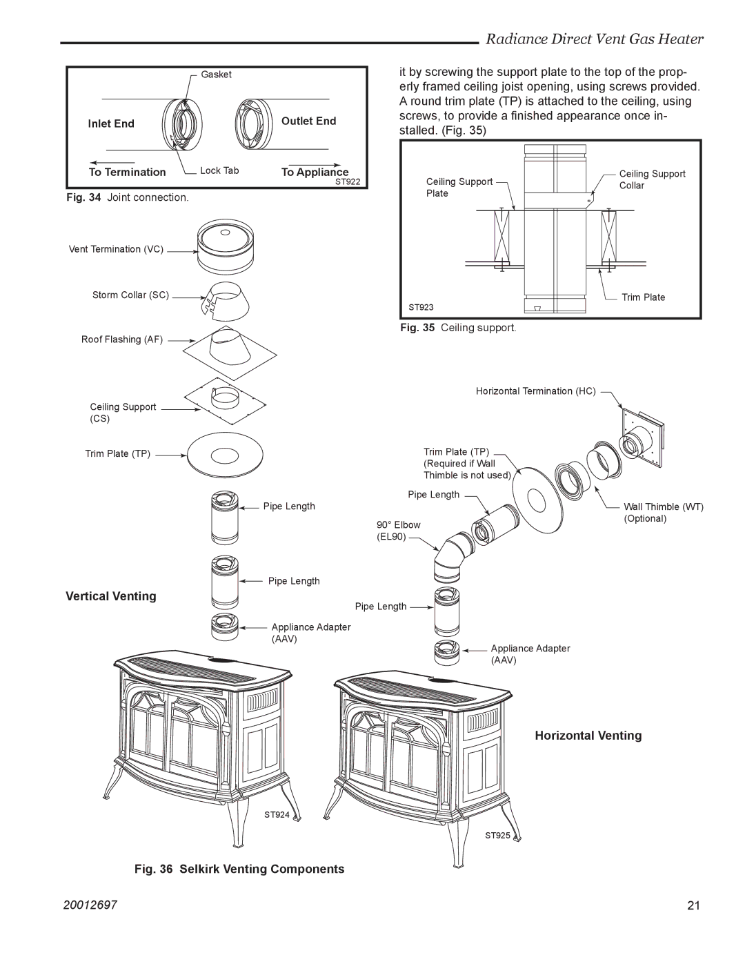
it by screwing the support plate to the top of the prop- erly framed ceiling joist opening, using screws provided. A round trim plate (TP) is attached to the ceiling, using screws, to provide a finished appearance once in- stalled. (Fig. 35)
To Termination | Lock Tab | To Appliance |
|
| ST922 |
Fig. 34 Joint connection. |
|
|
Vent Termination (VC) |
|
|
Storm Collar (SC) |
|
|
Ceiling Support Plate
ST923
Ceiling Support Collar
![]() Trim Plate
Trim Plate
Fig. 35 Ceiling support.
Roof Flashing (AF) ![]()
Horizontal Termination (HC)
Ceiling Support ![]() (CS)
(CS)
Trim Plate (TP) | Trim Plate (TP) |
| (Required if Wall |
| Thimble is not used) |
| Pipe Length |
| Pipe Length |
| 90° Elbow |
| (EL90) |
| Pipe Length |
Vertical Venting | Pipe Length |
| |
| Appliance Adapter |
| (AAV) |
| Appliance Adapter |
| (AAV) |
![]() Wall Thimble (WT) (Optional)
Wall Thimble (WT) (Optional)
Horizontal Venting
ST924 ![]()
ST925 ![]()
Fig. 36 Selkirk Venting Components
20012697 | 21 |
