Radiance Direct Vent Gas Heater
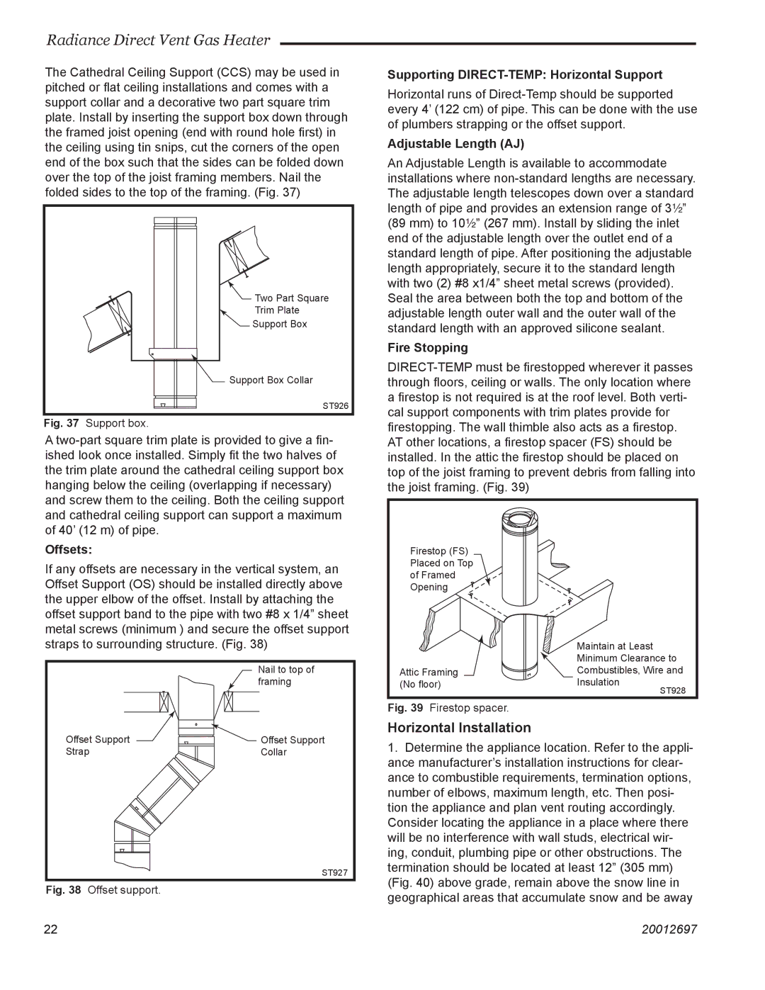
The Cathedral Ceiling Support (CCS) may be used in pitched or flat ceiling installations and comes with a support collar and a decorative two part square trim plate. Install by inserting the support box down through the framed joist opening (end with round hole first) in the ceiling using tin snips, cut the corners of the open end of the box such that the sides can be folded down over the top of the joist framing members. Nail the folded sides to the top of the framing. (Fig. 37)
![]() Two Part Square
Two Part Square
Trim Plate
Support Box
![]() Support Box Collar
Support Box Collar
ST926
Fig. 37 Support box.
A
Supporting DIRECT-TEMP: Horizontal Support
Horizontal runs of
Adjustable Length (AJ)
An Adjustable Length is available to accommodate installations where
Fire Stopping
Offsets:
If any offsets are necessary in the vertical system, an Offset Support (OS) should be installed directly above the upper elbow of the offset. Install by attaching the offset support band to the pipe with two #8 x 1/4” sheet metal screws (minimum ) and secure the offset support straps to surrounding structure. (Fig. 38)
Nail to top of framing
Firestop (FS) Placed on Top of Framed Opening ![]()
Attic Framing (No floor)
Maintain at Least Minimum Clearance to Combustibles, Wire and Insulation
ST928
Offset Support | Offset Support |
Strap | Collar |
ST927
Fig. 38 Offset support.
Fig. 39 Firestop spacer.
Horizontal Installation
1.Determine the appliance location. Refer to the appli- ance manufacturer’s installation instructions for clear- ance to combustible requirements, termination options, number of elbows, maximum length, etc. Then posi- tion the appliance and plan vent routing accordingly. Consider locating the appliance in a place where there will be no interference with wall studs, electrical wir- ing, conduit, plumbing pipe or other obstructions. The termination should be located at least 12” (305 mm) (Fig. 40) above grade, remain above the snow line in geographical areas that accumulate snow and be away
2222 | 20012697 |