Radiance Direct Vent Gas Heater
Termination Clearances
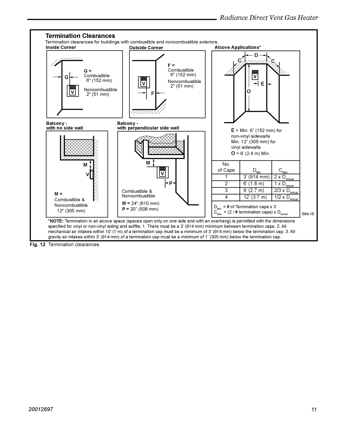
Termination clearances for buildings with combustible and noncombustible exteriors.
Inside Corner | Outside Corner | Alcove Applications* |
|
|
| F = |
|
| G = |
| Combustible | |
G | Combustible |
| 6" | (152 mm) |
| 6" (152 mm) | V | Noncombustible | |
|
| 2" | (51 mm) | |
| Noncombustible |
| ||
V |
| F |
| |
2" (51 mm) |
|
| ||
Balcony - | Balcony - |
with no side wall | with perpendicular side wall |
M | M | |
| ||
V | V | |
| P | |
M = | Combustible & | |
Noncombustible | ||
Combustible & | ||
M = 24" (610 mm) | ||
Noncombustible | ||
P = 20” (508 mm) | ||
12" (305 mm) |
![]()
![]() D
D ![]()
![]()
C C
V
![]()
![]() E
E ![]()
O
E = Min. 6” (152 mm) for
O = 8’ (2.4 m) Min.
No. |
|
|
of Caps | DMin. | CMax. |
1 | 3’ (914 mm) | 2 x DActual |
2 | 6’ (1.8 m) | 1 x DActual |
3 | 9’ (2.7 m) | 2/3 x DActual |
4 | 12’ (3.7 m) | 1/2 x DActual |
DMin. = # of Termination caps x 3
CMax. = (2 / # termination caps) x DActual
*NOTE: Termination in an alcove space (spaces open only on one side and with an overhang) is permitted with the dimensions specified for vinyl or
Fig. 12 Termination clearances.
20012697 | 11 |